
Beyond Blink Without Delay
If you’ve been building projects with Arduino-compatible microcontrollers for more than a few months, you’ve probably faced the challenge of orchestrating the timing of the processing functions for multiple switches, sensors, displays, LEDs, motors, etc. On your first simple projects, you probably got away with using one or more calls to the Arduino delay() function to implement fixed or variable delays within your main loop(). But you soon learned that the delay() function is blocking, meaning that the processor doesn’t advance to the next instruction until the specified delay time has expired. That makes it impossible to perform any other functions (except interrupts) concurrently with the delay.
So after a little research you likely found the Blink Without Delay tutorial, which opened up a new world of possibilities by recommending use of the millis() function to implement non-blocking delays. But…the example used in the tutorial is pretty simplistic, and doesn’t provide any guidance on how to use this method in more complex situations involving multiple tasks with overlapping and non-aligned timing requirements.
The goal of this article is to help you advance to that next level of sophistication. It starts by introducing a variant of the blink-without-delay method that is both easier to understand and simpler to implement. Next, it describes how to use this new method to address the variety of delay/timing scenarios that you’re likely to encounter. Finally, it describes a method to structure and modularize your code in a way that allows you to implement multiple concurrently-executing “tasks” while actually improving code readability.
And as an added bonus, you’ll be able to impress your friends by confidently explaining the difference between preemptive multitasking and cooperative multitasking.
Recap: Blink-Without-Delay Timing Method
First, let’s review the essential elements of the blink-without-delay method using the millis() function. In the example below, a single function called TaskA() is repeatedly executed every 50 milliseconds (ms).

The timelines below illustrate three scenarios that occur in the execution of the program above. In scenario (1) the value of PreviousTime has already been set in a previous iteration of the loop, and in each subsequent iteration the value of CurrentTime is updated with a new value returned by the call to millis(). With one exception (explained later), the millis() return value continuously increments with a resolution of one millisecond. In scenario (1) the difference (currentTime - previousTime) hasn’t yet reached the value of taskDelay, so the conditional expression evaluates to false and nothing interesting happens until scenario (2).

In scenario (2) the time difference between the two variables is just slightly greater than taskDelay, causing function TaskA() to be executed. Either before or after the call to TaskA()the value of previousTime is updated to reflect the time at which TaskA() was called. This leads to scenario (3), which is exactly the same as scenario (1) but with both timing variables “pushed down the road”. And repeat…
Note that it’s important to use the > operator instead of an equality operator (==). There’s no guarantee that the value returned by millis() won’t have increased by more than 1 ms between calls, regardless of how fast the main loop appears to be.
While the blink-without-delay method works perfectly well, there are three minor issues: First, the code implicitly relies on the fact that the millis() value is initialized to zero at the start of program execution. Since previousTime is explicitly initialized to zero, the first call to Task(A) should in theory occur 50 ms after the program starts. But this could be delayed If your setup() function takes longer than 50 ms to complete. So this method doesn’t allow you to accurately predict the execution time of the first task, or more importantly, to align task execution with an external event such as the edge of a switch input signal. More on that in the next section.
The next two issues are not really functional limitations; they’re just aspects of the method that frequently cause confusion. The first of these is perhaps trivial: the need to use two dynamically-updated variables (currentTime, previousTime) plus a call to millis() just to implement a repeated call to TaskA() at a fixed rate. The method described in the next section addresses this concern.
The final issue deals with the fact that the internal counter used by millis() is an unsigned long data type that is represented with 32 bits. After the value reaches (232 – 1) = 4,294,967,295 it will “roll over” to a value of 0 at the next millisecond count. This will occur every 49.71 days if your program runs continuously. This is illustrated in scenario (4) below:
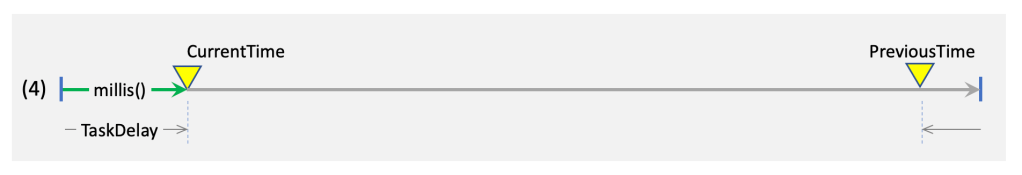
In this scenario, the last execution of TaskA() occurred before the time that the millis() value rolled over to 0 and resumed counting. Now the relationship between the two variables is seemingly reversed. But fortunately, due to the way that all processors implement unsigned binary arithmetic, the expression (currentTime - previousTime) will still return a positive value that, in this example, is just greater than taskDelay, causing TaskA() to execute as expected. This effect is referred to as wraparound. In the world of commercial software development, reliance on wraparound effects is frowned upon as it makes code harder to understand and may affect portability to other platforms.
elapsedmillis Timing Method
This method uses the simple but powerful elapsedMillis library originally written by Paul Stoffregen at PJRC (manufacturer of the Teensy line of microcontrollers). This library can be used with any Arduino-compatible microcontroller. Below is an example that can be directly compared with the blink-without-delay method.
The library implements a C++ object called elapsedMillis that allows an essentially unlimited number of timer variables to be created, as shown for taskTimer in the example. Any reference to taskTimer produces an unsigned long value that can be referenced in the same ways as any other variable. As with millis(), any elapsedMillis variable (object) is automatically updated using an internal timer with 1 ms resolution. The key simplification is that elapsedMillis objects can be reset to zero at any time, allowing the value to be directly compared with a task delay value.

In this example, all of the initialization steps are moved to the standard setup() function, and this requires that taskTimer and taskDelay be defined as global variables prior to their use in setup() and loop(). But as will be shown later, elapsedMillis objects can be defined within any program scope, including within a data struct.
The ability to set elapsedMillis objects to zero (or any value) eliminates all three of the issues with the blink-without-delay method described in the previous section. Most obviously it eliminates reliance on arithmetic wraparound, and reduces the number of variables and function calls involved, resulting in more readable code. Further, it enables synchronization of task execution with other events. Specifically, the step taskTimer = 0 can be performed at any time to align the execution timing of TaskA() with other tasks or external events. This will be described in more detail later in this article.
In the example above, note that taskTimer is reset to 0 immediately after its value is determined to exceed the value of taskDelay, in preparation for subsequent comparisons of the two values. This is necessary to avoid any “time slippage” that might occur if there were a long delay between the comparison and reset steps.
The are also similar libraries called elapsedMicros and elapsedSeconds that may make sense to use for timing shorter or longer intervals. All of the examples in this article used elapsedMillis, which can be used to implement delays of up to 49.71 days.
Example 1: Switch Debounce
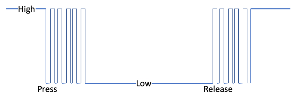
Now let’s explore some slightly more complex scenarios involving synchronization and variable time delays, but still using only a single elapsedMillis timer. The first example shows how to debounce the input from a momentary-action pushbutton switch. Assuming that the switch is connected between Ground and a GPIO input signal on pin 2 (with the internal pull-up resistor enabled), the signal waveform is likely to look like the diagram at right. The signal level that is read by the Arduino processor will “bounce” between high and low logic levels both when the switch is depressed and when it is subsequently released. Depending on the specific switch used, the signal may require 10’s of milliseconds to settle to a stable value. A hardware debounce circuit (using a resistor-capacitor filter) can reduce the amount of signal bounce, but may not eliminate it completely. For the best reliability, it’s wise to employ both hardware and software debounce techniques.
In this example, the goal is to periodically sample the switch input and print a single message for each time the switch is pressed. Without debouncing, the software would detect what appears to be multiple presses each time the switch is depressed and released. The debounce technique used in the example is to detect a falling edge (high-to-low transition) and then impose a “lockout” period (100 ms in this example) during which the switch input is essentially ignored. A single switch press event is reported. After the lockout period has ended, the switch input should be at a stable low level. Then, when a rising edge is detected, the lockout period is again imposed, but this time no switch press event is reported.
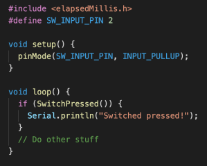
The code snippet at right shows just the setup() initialization and the loop() function, which calls the boolean function SwitchPressed() to determine if the switch has been pressed. Note that SwitchPressed() must return a true value only once for each time the switch is pressed.
Below is the definition of the SwitchPressed() function. All of the debounce-related variables are defined within the scope of the function definition, rather than as program-scope global variables. This type of “encapsulation” hides the low-level details that would otherwise make the other parts of the program harder to read and understand. Note that three of the variables, including the elapsedMillis object, are defined using the static modifier. This allows these variables to retain their values in between calls to the function, unlike the other variables that are initialized for each call. In the case of the elapsedMillis object, debounceTimer continues continues counting between calls.

Notice that the usage of elapsedMillis is somewhat different than that in the introductory example in the previous section. In that case TaskTimer was used continuously and periodically reset to 0. In this example, usage of debounceTimer is triggered by an external event (switch edge), and after the end of the lockout period its value is ignored until the next trigger event. This is an example of how elapsedMillis supports the synchronization of task timing with external events.
SwitchPressed() is a non-blocking function, meaning that even though it implements the switch lockout delay on both signal edges, it still returns to the main loop() fairly quickly. That characteristic is key to the efficient execution of many concurrent tasks in a more complex application.
Example 2: Variable Duty Cycle LED Blink
In this example, the code blinks an LED at a fixed rate, but with a variable duty cycle: the ratio of the on and off durations. The pushbutton switch from Example 1 is used to control the duty cycle. The duty cycle starts at 0% (completely off), and each pushbutton press increases the duty cycle by a fixed amount until the LED remains constantly on (100% duty cycle). The next press returns the duty cycle to 0%, and so on.
This example demonstrates the ability to use a single elapsedMillis object to implement two different delay durations, one for each portion of the cycle. As shown in the first section of code below, a global data structure called led is defined to hold all of the state variables related to the LED. These variables are initialized by setup().

Next we add a simple function to increase the duty cycle each time it is called, with the desired behavior of resetting back to 0% duty cycle after the button is pressed enough times:

This makes the main loop() really simple:

Note that IncreaseDutyCycle() is only called when the pushbutton switch is pressed, but the function UpdateLed() is called in every loop iteration. Since not much else is going on, it will get called very frequently! That’s OK, and is actually key to the multitasking methodology that will be described in the next section.
Here’s the definition of the UpdateLed() function:

This should be self-explanatory, but the key point is that led.timer is compared to different delay values depending on the current value of led.state. Some of the other conditional logic is needed to avoid turning the LED on (even very briefly) when the duty cycle is 0%, or turning it off when the duty cycle is 100%.
Also note that the digitalWrite() function is only called when it’s necessary to transition the LED between the on and off states. So for the vast majority of calls to UpdateLed(), nothing actually happens. But that’s OK!
Intro to Multitasking
Many modern microprocessor chips contain multiple processor cores that allows the chip to perform multiple tasks simultaneously. But since none of the microcontrollers available for use in the Arduino environment are multi-core, a different approach called concurrent execution is used to give the appearance of simultaneity, albeit with lower performance. In a concurrent approach, the execution of multiple software tasks is interleaved in a way that allows the overall performance goals of the system to be met. The key to the success of this method is to prevent any single task from “hogging” the processor such that other tasks are blocked from executing when necessary.
There are several different methods used to implement single-processor, concurrent multitasking. The most sophisticated method uses an operating system (OS) to actively schedule the execution of each task based on defined task priorities and other considerations. The scheduler function within the OS uses interrupts to force switching among tasks at defined intervals or in response to external events (e.g., keyboard input). This method, referred to as preemptive multitasking, is used by all the usual suspects (Linux, MacOS, Windows) as well as real-time operating systems (RTOS) for embedded control applications.
In the standard Arduino environment there is no operating system. Once execution of a sketch starts, there is no “scheduler” available to help orchestrate task execution. That leaves it up to your tasks (modules of code) to cooperate among themselves to efficiently share the single processor. This is called cooperative multitasking and is the focus for the remainder of this article.
Cooperative Multitasking Guidelines
The previous examples illustrate some of the basic principles of cooperative multitasking, but here’s a more comprehensive list:
- Clearly identify the distinct sets of functionality within your program, especially the ones with unique timing requirements. Group all of the code associated with each of these “tasks” into a small set of similarly-named function calls. Ideally, but not necessarily, move the function definitions for each task into a separate .ino or .cpp file.
- As with SwitchPress() and UpdateLed() in the previous examples, write the code for each function so that it quickly determines if any action is required, and returns quickly if not.
- Call each task sequentially from the main loop(). Arrange the sequence of function calls to achieve the best performance, taking into account the minimum and maximum amount of time that each function will require to execute.
- Don’t use any blocking functions such as delay(), unless the maximum blocking duration is small enough that it can be accommodated. For example, it may be acceptable to use delayMicroseconds() to create a small delay between successive messages sent across a hardware interface (like I2C).
- If hardware interrupts are used to respond to external events (e.g. character received on a serial interface), minimize the amount of processing performed within the interrupt service routine (ISR). Perform only the most time-critical steps, and then set a flag that will be detected by a higher-level task that performs the remaining steps.
The following sections expand on these guidelines to show how very complex multitasking behavior can be achieved in a “real world” application.
Multitasking Example
The photo below is of a custom controller board that I use to implement LED lighting for art installations.

This board incorporates a Teensy 4.0 microcontroller and contains many features that operate concurrently using the approaches described in this article:
- Five addressable LED strip interfaces, with each interface supporting multiple animation effects
- Four general-purpose PWM outputs that can be used to drive non-addressable (analog) LED strips or small DC motors, with smooth PWM duty cycle ramping functions
- A micro SD card that contains an interpreted-language script that orchestrates the operation of the board using time-tagged script commands.
- Two switch inputs that can be used for script triggering or mode selection, with capabilities to detect multiple switch “gestures”, e.g., double-tap, long-press, etc.
- An interface to a passive infrared (PIR) motion sensor, used for script triggering
- A differential-I2C interface to a remote ambient light sensor, used to adjust LED brightness in response to changing ambient light conditions. The software uses multiple timers to implement polling as well as timeout-based error detection and recovery
- A bi-directional RS-422 serial interface for communication with another controller or a user interface unit containing a liquid-crystal display and rotary encoder.
- A battery-backed real-time clock (RTC) that may be used to trigger script execution
A typical project uses about 10 separate tasks, often using multiple elapsedMillis timers per task. Many of these tasks, the ones associated with the LED and PWM outputs, are executed at a fixed “frame” rate with a period of between 10ms and 33ms. Even so, they use additional timers to implement longer timing intervals, for example to terminate an LED “flame-flicker” effect that has a script-specified duration.
The tasks associated with the switches and sensors use timers to implement periodic polling of the hardware interfaces, and additional timers for various types of timeouts.
The actual code is too lengthy to show here (~2500 lines). Instead the next section will explain the software design patterns that were used to create the code, and that you can apply to your own projects.
Design Patterns for Multitasking
This section expands on the guidelines described in a previous section, with a recommended approach to structuring your program into tasks that can be executed concurrently. There are many possible variations on this approach, so you should just consider this as a starting point to find the exact structure that works best for your application.
In this recommended approach, each task is a software module that consists of at least three function definitions: a Task_Init() function, a Task_Update() function, and a Task_Control() function. For each task in your program, substitute your preferred name for the word “Task” in the function names above. For example: Led_Init(), Led_Update() and Led_Control().
Each Task_Init() function should be called from setup() to perform any task-specific initialization functions, including:
- Initialize as necessary any variables and data structures used by the task
- Configure GPIO data pins used by the task as inputs or outputs
- Set output pins to the necessary initial state (high or low) as necessary
- Configure any peripheral I/O chips used by the task, possibly by calling a library function associated with the chip.
Each Task_Update() function is called from main loop(), and performs the main processing operations for the task. The UpdateLed() function in example 2 above is a good example of this type of task function (just with a different name format). Most “update” functions will use one or more externally-defined state variables (like the led data structure in example 2) to control the details of the exact processing to be performed.
A Task_Control() function is used to alter the behavior of the task, by changing one or more state variables that control the behavior of the associated Task_Update() function. In example 2, the IncreaseDutyCycle() function is a very simple type of control function. More typically, the control function will accept one or more parameters that specify the desired change. For example, the function could have been defined as:

With appropriate changes to the function body code, this would allow the main loop() or another function to directly set the duty cycle rather than be constrained by the fixed increment used in the example. Of course, it’s also possible to allow other functions to directly modify the variables in the led data structure, but this is considered to be a poor programming practice. It’s much better to use control functions that explicitly define the types of changes that can be made, and that “hide” the internal details of how the data structure is used. If you understand object-oriented programming (like C++), this advise will sound very familiar.
To improve program readability (and other reasons) it often makes sense to define multiple Control functions for each task, rather than use a single Control function with multiple unrelated parameters.
OK, now we have an Init, Update, and Control function defined for every task. The next step is to decide how to sequence and coordinate their execution. The Init functions are easy: these should be called sequentially from setup(). The exact sequence only matters if the initialization performed for one task is dependent on the initialization steps of another task.
The sequence of calls to the Update functions within the main loop() depends a bit on your specific application. Here’s a simplified summary of the sequence used in most of my projects:
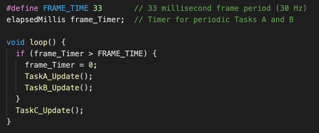
I usually have several tasks that all need to execute at the same frame rate, where the exact sequence is important. To ensure the correct sequence, I use a single timer in the main loop(). When the timer expires, after resetting it to zero I call the “high-priority” tasks, represented here by TaskA_Update(). In my case, these are tasks that usually take the same amount of time to execute each time they are called. An example is a task that reads pixel data from a fixed-size buffer, performs color conversion/correction algorithms, and then sends RGB pixel data to a set of LED strips.
The lower-priority tasks, represented by TaskB_Update(), still need to execute at the same frame rate but often have a highly-variable execution duration. An example is a function that generates pixel data based on a higher-level mathematical model (e.g., a sinusoidal wave). The execution time depends heavily on the complexity of the animation specified by the script and the number of pixels involved. Note that the data generated by TaskB_Update() is used by TaskA_Update() in the next frame, but that one-frame delay (or latency) doesn’t matter in my application. It’s more important that the successive execution times of TaskA_Update() in each loop iteration are equally spaced. This minimizes task execution timing jitter that might cause visible artifacts.
TaskC_Update() is representative of tasks that need to run at a slower rate, or in response to external events. These tasks implement their own timers internally, like the SwitchPressed() function in example 1.
The exact nature of the Control functions obviously depends quite a bit on the type of task processing performed by the associated Update function. In my applications, the timing of script command execution is determined by a task represented by TaskC_Update(). When each script command is executed to start a new LED effect, TaskC_Update() calls one of the Control functions for TaskB. This sets the internal TaskB_Update() parameters to initiate the specified effect.
Timer Overrun
When coding a complex multitasking application, it’s very difficult to estimate the maximum time each task will require to execute. All of the examples shown above assume that the the comparison of an elapsedMillis timer with the desired time delay value will be executed frequently enough that it won’t “miss” the time at which the timer value just reaches and then exceeds the time delay value. However, if one of the tasks takes longer than expected, the timer may significantly exceed the delay value before the condition is detected. This condition is called timer overrun, and it may result in unexpected program behavior.
During program development, it may be wise to “instrument” your code to detect and report timer overrun conditions that exceed a certain threshold, perhaps as small as 1 ms. This can be accomplished with a minor modification to the timer comparison, as shown below using the main loop() from the previous section as an example.

The reporting function could be as simple as immediately printing a message, or more sophisticated by gathering statistics for reporting on a periodic basis.
Need More?
Congratulations for making it this far! Hopefully you’re inspired to start experimenting with the multitasking approach described above. But if these techniques don’t quite float your boat, I’ll mention three other avenues to explore.
The first option is the Arduino Ticker library, which supports the ability to call Update-type functions at pre-defined intervals. For applications needing only periodically-executed tasks, the Ticker library may provide a somewhat cleaner solution than elapsedMillis. For my own projects, with a variety of task types and timing requirements, I found that it was easier to use elapsedMillis for everything and eliminate an extra library dependency.
If you’re building an LED project, you may already be familiar with FastLED. This library provides an EVERY_N_MILLISECONDS call to execute functions or code segments on a periodic basis. There is also a variant called EVERY_N_MILLISECONDS_I that allows the execution period to be changed dynamically. This capability is frequently used in programs that rely on FastLED’s many other features, but may also be used to implement multitasking for non-LED projects, with minimal memory overhead.
Finally, if you’re ready to handle a significant step up in complexity, you can use a true real-time operating system (RTOS) such as FreeRTOS. Adaptations of FreeRTOS are available for a variety of processors (such as the AVR family) and can be used within the Arduino programing environment or alternatives such as PlatformIO.
While an RTOS will provide much more capability and flexibility than the methods described in this article, the associated overhead makes it unlikely that you’ll be able to achieve the same level of timing resolution or accuracy.
This is a far from exhaustive list, so feel free to break out the Google machine to find many other options.

what if you have a a user interface with a relative slow display and want todo other things faster?
LikeLike
That’s a great question! Sorry for taking so long to get back to you. The typical technique in a situation like this is to use a buffer that is filled by the “fast” clients that want to post a message to the display, combined with a “server” function that writes data from the buffer to the display. Create a client-side interface to the buffer, with function calls like SendDisplayMessage(char *msg) that appends the character string to the buffer and then immediately returns. The “display server” function is a little trickier, since it needs to do its work on a “time sliced” basis. Create a DisplayServer() function that gets called in every iteration of the main loop. When DisplayServer() is executed and it sees that there are characters in the buffer, it pulls SOME of them out and sends them to the display. The number of characters to be sent by DisplayServer() for each call depends on the display speed and how long your other functions can afford to wait for another turn to be executed from the main loop. Please let me know if that’s unclear or if you have other questions.
LikeLike