After a 2 month hiatus to focus on other projects, I now have some progress to report on.
FidoLight Summary
A compact 10W RGBW spotlight with an intelligent driver that can be controlled via a multi-drop/addressable RS-422 serial bus. The driver board supports high-level lighting effect commands such as Fade <to color> <duration> .
Microcontroller
As noted in previous updates, I had planned to use an ATMega328p microcontroller chip on the driver board. However, three issues have caused me to change course:
- The global chip shortage has made these parts very difficult to find, especially in the desired package type.
- The AVR (ATMega) family of chips nominally support PWM outputs with only 8-bit resolution, which is inadequate to achieve smooth brightness fades. It’s possible to achieve higher PWM resolution on two channels, but four channels are needed for this project. Software bit-banging techniques can be used to achieve higher resolution on all four channels, but would leave very little CPU bandwidth available for other functions.
- This processor is a bit underpowered to perform some of the intended functions (e.g. color space conversion, Gamma correction) that benefit significantly from a floating point execution unit.
So I decided to stick with the same microcontroller unit (MCU) board that I use for all of my other projects, the Teensy 4.0. As with my other projects, the Teensy 4.0 MCU board will be mounted to my custom PCB on header pins.
While this incurs a significant cost increase, it brings a lot of additional performance and capability:
- At least 200x faster than the ATMega328p
- 64-bit floating point unit
- Much larger Flash memory and RAM
- 16-bit PWM channels
- USB interface for firmware upload (eliminates need for external FTDI and/or ISP adapters)
Circuit Design/PCB
As noted in update #2, I originally planned to use the AL8861 buck LED driver, but switched to the Richtek RT8471 for the first pass of the PC board design.

Unfortunately, I wasn’t able to get this part working correctly, likely a result of poor component/value choices and bad layout decisions on my part. On top of that, I smoked the MCU chip by accidentally applying 12v to one of the I/O pins. Oops!
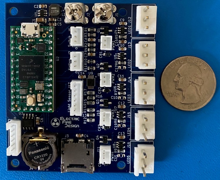
While I was crying over those setbacks, I discovered that availability of the Richtek driver chip had completely dried up. So…I switched to yet another chip, the Texas Instruments LM3405. This one requires a few more external components, but allows me to use a much smaller inductor. Also, it has an excellent data sheet/application notes, so I was more confident that it would work. And it did! Here’s version 2 of the PCB, with the Teensy 4.0 MCU mounted on the back side.
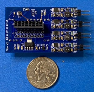

Note that I had to switch to a different voltage regulator also (12v to 5v), since availability of voltage regulator chips is also a moving target. This version of the board was designed to accommodate either a Teensy 4.0 or an Arduino Pro Mini MCU board, as their form factors and pinouts are somewhat compatible.
My initial testing of the v2 board showed that the LED driver circuits generated more heat than I was expecting. With the sense resistor value selected to provide 1A of constant-current drive to each LED, the driver chip went into thermal shutdown mode within 30 seconds. Configured for 660mA of drive current, the board temperature rise was about 25ºC with no air cooling or heat sink. Toasty!
After going back to the data sheet and actually calculating the power dissipation in the driver chip and the external support components (should have done this first!), I realized that this board will need a heat sink, and that the plastic enclosure I had selected was inadequate to support this. I also needed to massage my component choices to somewhat reduce the power dissipation (e.g. inductor with lower DC resistance).
I just finished the v3 board design and have sent it to PCBWay for fabrication.

The major changes to the design include:
- Switched to all SMT connectors to eliminate bottom-side protrusions, enabling the board to be thermally mated to to the new aluminum enclosure (see next section).
- Maximized board area (based on the enclosure dimensions) for better thermal dissipation.
- Used the same 8-conductor push-in terminal block for the LED connections as used for the serial bus connections (upstream, downstream).
- Added mounting holes for M2.5 screws into enclosure bottom.
- Eliminated support for Pro Micro MCU.
- Changed the RS-422 serial bus to use 3.3v signal levels, eliminating the need for a level shifter to the 3.3v MCU.
- Started using 0603 SMT components (vs. 0805) wherever possible, now that I’ve demonstrated my ability to reliably solder these parts with my hot air station (and without a microscope!).
Enclosure/Cabling

The v1 and v2 PCB boards were intended to be mounted intro this very small plastic, waterproof enclosure. In addition to the thermal issue noted above, this enclosure would have made field installation very challenging. Although the cable to the separate LED housing would typically be pre-installed, the serial bus connections would usually be installed in the field. This involves feeding the waterproof Cat5e cable through the cable glands, stripping the individual wires, and pushing them into the appropriate slots in the terminal blocks, all within a very confined space.

To address the thermal and field wiring issues, I selected this cast aluminum enclosure, which is approximately 115mm (4.5″) x 65mm (2.6″) x 30mm (1.2″). Again, more expensive than the original plan, but probably necessary to achieve a robust, reliable product. I’ll use the same plastic cable glands as shown above.
To provide the thermal bond between the PCB and the enclosure bottom, I have a choice of three methods:
- Thermally-conductive adhesive
- Thermal paste (grease) with hold-down screws
- Thermally-conductive silicon pad with hold-down screws
My current plan is to use thermal paste/screws. The back side of the PCB is a large ground plane, and there are lots of vias to the top-side ground pads of the “hot” components. The ground plane will be completely covered with solder mask, which is non-ideal thermally, but eliminates other issues with exposed copper. It’s very possible that I’ll revise this approach after some testing.
Color Space Conversions
In update #1 I mentioned that the command set would use the HSV color space for color specification. Since then, I re-discovered a series of articles that convinced me that the HSI color space was actually better. The author also provided an excellent algorithm for conversion from the HSI color space to RGBW, fully utilizing the W (white) channel to achieve unsaturated (“pastel”) colors. I’ve been successfully using HSV-to-RGB transformations for a while, and I’m confident that HSI-to-RGBW will work even better. I contacted the author to ask some follow-up questions, and he was very helpful even though he wrote the articles in 2013.
Wrap-Up
That’s about it for now. I’ll receive the v3 boards in the second week of September 2021, and will provide another update based on my test results.

One thought on “FidoLight RGBW Spotlight: Update #3”