Well, there’s been lots of progress on upgrading my woodworking shop, but I won’t bore you with that. Somewhat less progress on the various “big” lighting projects, but there are a few updates on my FidoLight project that I think you might enjoy hearing about.
As you may recall, I’ve been working for a couple of years on the design of a custom, high-power RGBW spotlight. For the truly curious or demented, I’ve assembled here the links to all of the updates I’ve posted over that time: The_Beginning, Update #1, #2, #3, #4, #5, #6, and #7. Wow, how can I not be done yet?

I haven’t had a specific project in mind to use these for, except to light my back yard. But now my artist friend Peter Hazel is in a competition for a large outdoor art installation in Colorado. He’s proposing a stand of stainless steel and glass Aspen trees, each at least twenty feet (6m) tall. He wants to hide spotlights in the branches to illuminate the glass leaves. Even though my existing design (photo at right) is pretty small, it would still be too conspicuous. So I went hunting for a slimmer enclosure that could be mounted inside the tip of a “broken” branch.
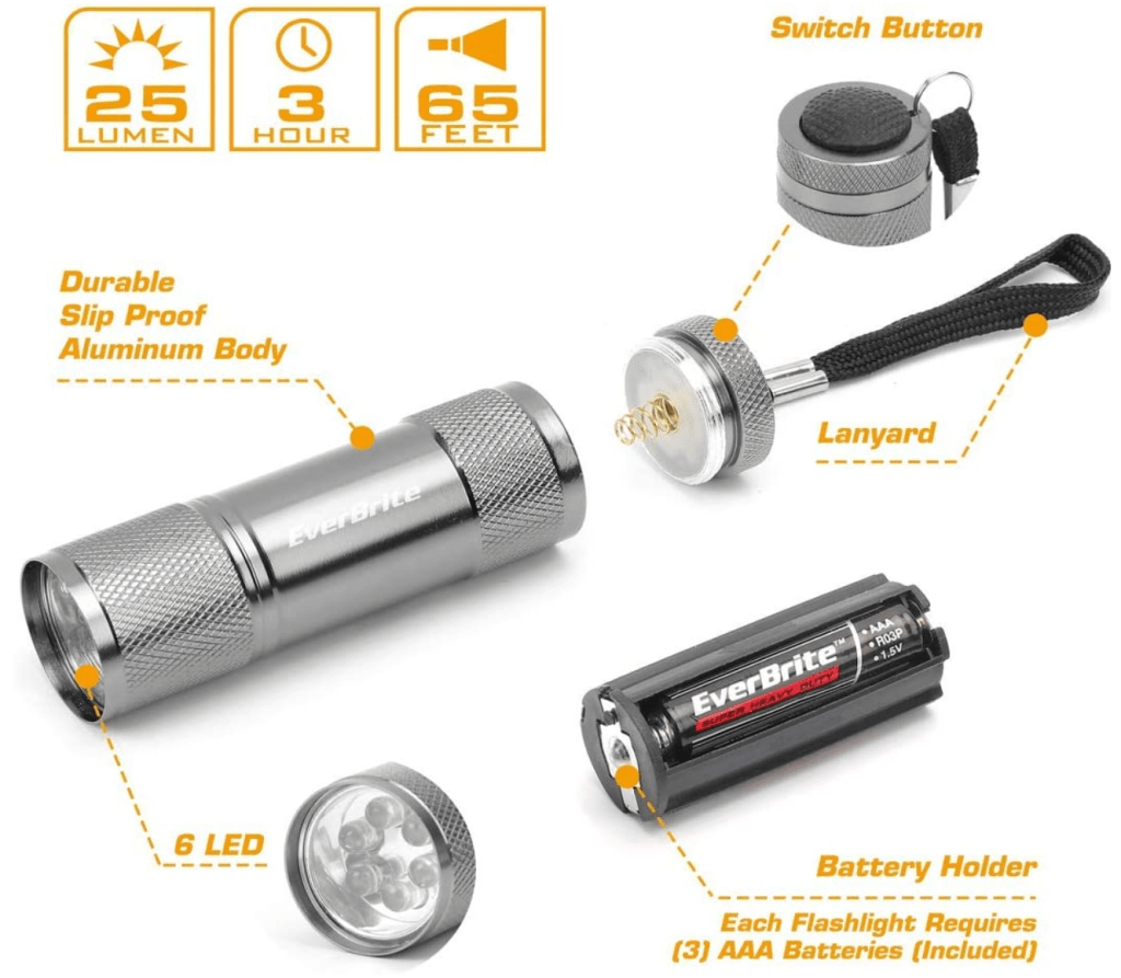
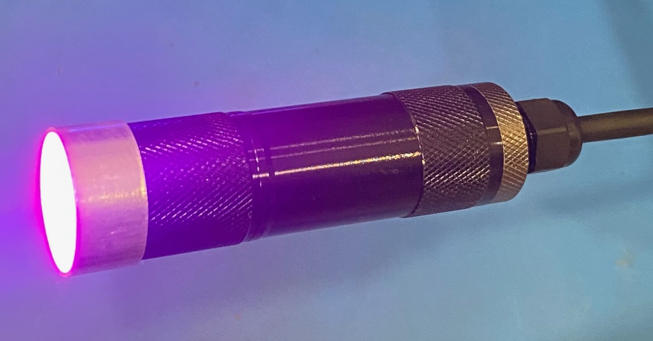
I immediately latched on to the idea of using a flashlight enclosure, and I remembered a box of dirt-cheap LED flashlights that I had bought to use around the house. “What if”, I thought, “the flashlight enclosure were perfectly sized to accommodate all of the FidoLight components, and also lent itself to being fully waterproofed?”.
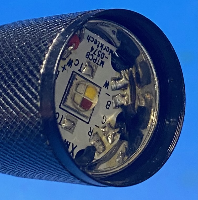
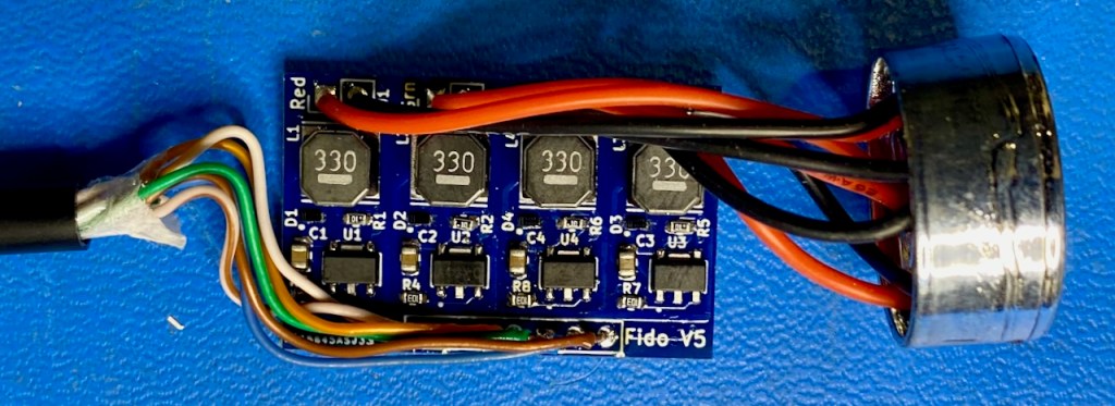
Apparently miracles do sometimes happen. It was easy to completely disassemble the flashlight, and the 20mm Cree XLM LED module (mounted on the Martech starboard module) fits perfectly inside the LED mounting plate in place of the flashlight LEDs. Even more amazingly, my existing Fido v5 PCB slides nicely inside the flashlight body. And the on/off switch can be easily removed, leaving a hole just the right size to install a PG7 cable gland.
The aluminum housing is quite rugged, but the existing plastic lens was a bit thin and seemed like it would be difficult to waterproof at the edges. So I cut short sections of aluminum tubing (25mm I.D.) that serve as a collimator to narrow the beam, and also accommodate some beefier 25mm acrylic discs. Fortunately, the diameter of the smooth flange at the front end of the flashlight housing is exactly 25mm, so the aluminum tube section press-fits tightly onto the housing, and the lens press-fits into the tube section.

I used CA adhesive (“super glue”) to bond the large nut of the cable gland to the inner flange of the threaded back end of the flashlight housing (former location of the on/off switch). I then applied exterior-grade silicone sealant to fill the small gaps around the cable gland. I used a small syringe to apply a narrow ring of sealant around the front face of the lens. I still need to do more extensive water-resistance testing, but the results of a quick “heavy rain simulation” were promising.
In low quantities, the per-unit cost of the flashlight and other housing components (no electronics) is only $2.50 USD. Not bad, and I end up with lots of spare AAA batteries!
The one thing I haven’t mentioned yet is thermal performance. The maximum power dissipation for a single color/channel is about 4W, so in theory the worst-case LED power dissipation is 16W. But that doesn’t make sense, turning on the R, G, and B channels at full brightness (making white light) and also turning on the W (white channel). I recently realized that it doesn’t even make sense to turn on two channels at full brightness. For example, combining full-intensity blue plus full-intensity red makes magenta, but it will be much brighter (nominally twice as bright) as the individual blue or red hues. That would result in undesirable brightness changes when attempting to smoothly fade between two single-channel hues. Uniform brightness is maintained when the sum of the individual component intensities is maintained at a constant value over the duration of the hue fade. So halfway through a fade from full-brightness red to full-brightness blue, the red and blue channels should both be at half brightness, resulting in a magenta hue that’s about the same brightness as the individual full-intensity hues. Actually it’s not quite that simple given the realities of LED physics and the eye’s varying sensitivity to different light frequencies. But, close enough for this discussion…
So the tldr here is that the maximum real-world LED power dissipation is only 4W. Since the driver circuit is 82% efficient, that means another 0.9W will be dissipated by the components on the driver PC board. At that power level, I don’t think I need to mechanically connect the PCB to the housing for thermal transfer purposes. Air convection and radiation to the metal housing should be sufficient. But the LED module could get quite toasty, and the plastic LED mounting plate doesn’t provide a good thermal path to the aluminum housing. So I need to come up with an aluminum mount for the LED module, ideally something that looks like a bottle cap. Hey….what about…a bottle cap!

It turns out there’s a standard aluminum screw cap that’s extremely cheap ($0.11 each) and almost exactly the right size. The diameter of the lip of this cap is 22.9mm. I just need to drill 6 holes for the wires to run through, and attach the LED module with thermally conductive adhesive. I’ll be receiving these caps next week, and have high hopes.
OK, so I’m still not done with this project, but I’m happy with the progress. I’m now building four complete units that I’ll subject to further thermal and environmental tests. I’ll be driving them with a single Flex controller board, and I’ll code up some cool animations that I can show Peter (and share in the next update).
Thanks for reading, and let me know what you think!
P.S. Check out the Index page for additional articles that you may find interesting.

Absolutely love when something conveniently happens to be the right size. 🙂
LikeLiked by 1 person
Yeah, amazing how well it worked out here. Not always the case…
LikeLike