
Part 1 of this article series presented an overview of the LED types most commonly used in art applications. Part 2 expands on that material with a discussion of LED optical characteristics and an overview of the additional optical elements most often used: diffusers, reflectors, and lenses.

Squared, Charles Gadeken 
Iceberg, ATOMIC3
Introduction
A discussion of LED optics requires a basic understanding of the metrics and units used to describe light intensity and directionality. While this can be a complex topic in general, it is simplified here to provide some information that almost everyone will find useful.
Luminous flux: a measure of the perceived total power of a light source, taking into account the sensitivity of the human eye to different color wavelengths. The unit of measurement is the lumen (lm). It’s important to note that luminous flux accounts for all light emitted in all directions from a device. Therefore the “lumen rating” of an LED isn’t useful for comparing different devices unless they have a similar beam angle (see below).
The luminous flux of an RGB LED is often (but not always) specified in the device data sheet. Sometimes the lumen values are broken out per color, and sometimes a single value (the sum of all colors) is provided.
Beam Angle: All of the LEDs described in this article are designed to throw light in the same general direction; that is, all of the emitted light beams will travel in a direction that is less than 90 degrees from the axis perpendicular to the face of the device. The light is most intense along this central axis and falls off as the angle of a beam approaches 90º, as illustrated in the typical plot below (the effect is 3-dimensional although the plot is only 2-D). The beam half-angle (⍬½) of an LED is specified as the angle at which the light intensity drops to one-half of the level at 0º. So in the plot below ⍬½ = 60º.
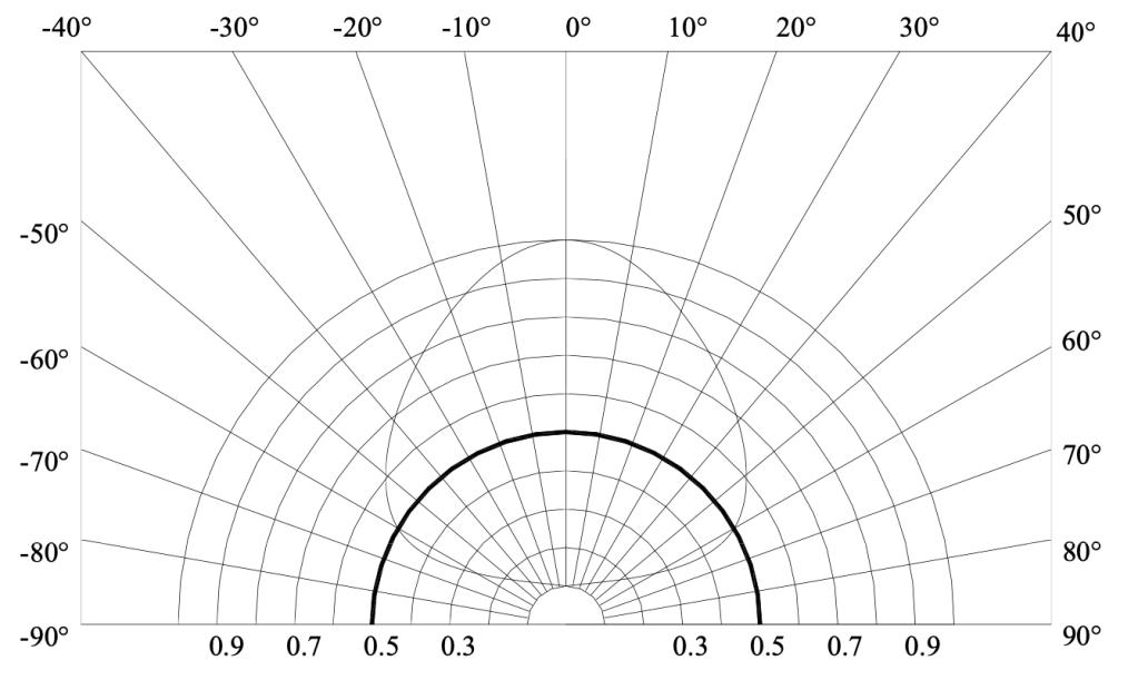
The full beam angle (⍬) is sometimes referred to as the Full-Width Half-Maximum (FWHM) beam angle, which is typically 120º for the types of SMD LEDs discussed in this series, regardless of their power level or specific package type. And just to be confusing, some manufacturer’s data sheets refer to the FWHM beam angle as 2⍬½.
Luminous Intensity: A measure of perceived light power in a specific direction, again taking into account the varying sensitivity of the human eye to different colors. This metric is much closer to approximating our perception of relative “brightness” when looking directly at a light source. The unit of measure is the candela (cd), or more typically the milli-candela (mcd).
Some LED manufacturers provide per-color or total luminous intensity (mcd) specifications in lieu of luminous flux (lumen) specifications, making it difficult to compare devices from different manufacturers. Fortunately there’s an easy conversion for LEDs with a 120º beam angle:
flux(lumens) = π • (intensity(mcd) / 1000), where π = 3.14Whew! Still with me? Now on the main topic here: the use of additional optical elements to achieve a desired lighting effect.
In the context of light art, the most commonly used optical elements are diffusers, reflectors, and lenses. All of these elements have the effect of either increasing or decreasing the effective beam angle of the light from an LED. This means that the effective luminous intensity (“brightness”) of a light source can be changed (in a specific direction) while the total light power (luminous flux/lumens) from the device remains the same. This becomes intuitively obvious when you think about twisting the head of a variable-beam flashlight: you can throw a very bright but narrow beam or a less-bright wider beam, while consuming the same amount of electrical power in the light source.
Diffusers
Anyone who has slapped some LED strips on their walls or their Burning Man art car immediately wished that the individual LEDs were not so distinguishable as individual point light sources (aka “hot spots”). One solution is an optical diffuser, but some understanding of beam paths and diffuser materials is required to achieve the desired results.
A diffuser relies the properties of optical diffraction and refraction to randomly scatter the angles of light beams that pass through it. As shown in the LED beam angle diagram above, luminous intensity is highest in the central axis of the device and falls off as the beam angle increases. The addition of a diffuser in front of an LED will make the light intensity appear more uniform across the entire beam, and will “soften” the edge of the beam. If LEDs in a strip are spaced close enough together, and if the diffuser is mounted at an appropriate distance from the LED lens surface, the resulting light will appear as a continuous bar of light. This requires a significant amount of overlap in the beams of adjacent LEDs at the viewing face of the diffuser. The minimum beam overlap to achieve acceptable diffusion is about 50%, as illustrated in the diagram below.
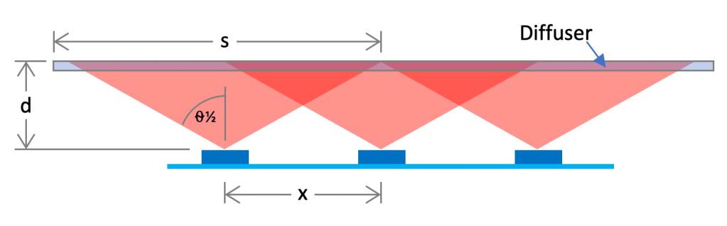
- The spacing between LEDs is defined as x, as shown in the diagram above. For example, using a strip with 60 LEDS/meter, x = 0.656″.
- The distance between the top of the LED lens and the viewing face of the diffuser is defined as d.
- The beam spread s is defined as the diameter of the beam at the diffuser face. This can be computed as s = 2 • d • tan(⍬½)
- To achieve 50% beam overlap: For a given LED strip with spacing x, mount the diffuser at distance d such that the beam spread s is twice the LED spacing (x). That is, s = 2 • x.
- Rearranging the formula for s above results in d = s / (2 • tan(⍬½)). Now substituting for s as defined by the rule of thumb, d = (2 • x) / (2 • tan(⍬½)) which simplifies to d = x / tan(⍬½). For ⍬½ = 60º this further simplifies to
- d = x • 0.58

So with a 60 LED/meter strip, 50% beam overlap (and potentially adequate light diffusion) is achieved by mounting the diffuser with the face at least 0.38″ above the top of the LEDs. This should be considered a rule of thumb, and experimentation may be required to get acceptable results. Fortunately, pre-fabricated aluminum extrusions (channels) with mating diffusers strips are available in a wide range of shapes and dimensions to accommodate most situations.
There are some important tradeoffs to consider in selecting a diffuser material. The amount of light scattering is affected by the material thickness, surface finishes and by the inclusion of microscopic refractive particles. However, the same factors that provide good scattering (high diffusion) also reduce the amount of light that is actually transmitted through the material, either through absorption or reflection from the inside surface. Again, experimentation with different diffuser materials may be required to get the desired results.
Unlike with other types of optics, it’s relatively easy to fabricate custom diffusers using specialized acrylic or polycarbonate sheet material that is available from many plastics suppliers. For example, the manufacturer Acrylite makes acrylic diffuser sheets with the brand name Satin Ice that are available in a wide variety of colors, thickness, and diffusion/transmission levels.
Reflectors
OK, this was a bit of a tease; reflectors, unless used with additional optical elements, aren’t very useful for color art lighting applications. While parabolic aluminized reflector (PAR) lights and ellipsoidal reflector spotlights are commonly used in stage lighting, these utilize high-intensity monochromatic light sources with a small emissive area approximating a point source. They are most often used to generate very narrow, high-intensity beams that aren’t useful for art applications. Also, color beams are achieved using plastic film filters (“gels”) rather than a color light source.
The multifaceted reflectors (MR) used in residential halogen light bulbs could in theory be used with a high-power RGB LED, but performance would be non-optimal. First, the use of three physically-separated LEDs within an RGB device results in slightly different beam paths from the emitter to the sides/facets of the reflector. This results in “color fringing” at the edges of the beam projected on the artwork.
Second, reflectors have the inherent property that only some of the emitted light beams are reflected, while most beams travel directly from the emitter to the subject. This means that reflectors can’t do much to compensate for the non-uniform intensity of LEDs as a function of beam angle, as illustrated in the diagram earlier in this article.
Third, round reflectors of this type can only be practically used with a single LED. Even with a high-intensity RGB LED, the total luminous intensity wouldn’t be sufficient for use as a flood light in a reflected-view lighting application. Most flood lights designed to illuminate a subject from 20 feet or more use at least 6 medium- or high-power LEDs. It’s interesting to note here that most low-end RGB LED flood lights incorporate a smooth or faceted reflector with a truncated-pyramid shape. It appears that these reflectors do very little to shape or control the collective beam angle, and only serve to reflect the light beams that are emitted from the LEDs at angles beyond the specified beam angle of the fixture.
And finally, reflectors aren’t very useful for art lighting applications because there’s a better solution, as described in the next section.
Lenses

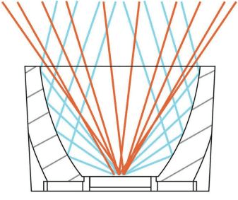
Forget what you learned about optics in high-school physics class; a new type of lens has arrived on the LED lighting scene. It’s called a total internal reflection (TIR) lens, and it’s actually a hybrid of a refractive lens and a reflector. Because they can be made inexpensively from molded poly(methyl methacrylate) (PMMA) acrylic, TIR lenses have become pervasive in LED light fixtures across many applications.
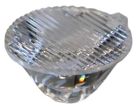
A TIR lens uses a molded refractive element to direct light beams toward the outer lens surface such that the beams are then reflected outward at the desired beam angle. Unlike a reflector-only design, all light beams emitted from the LED are subject to optical path modification based on the intent of the specific lens design. Additional optical features on the lens surface provide opportunities for further path modification (.e.g., diffusion).
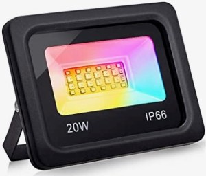
TIR lenses are still unlikely to produce perfect results when used in conjunction with multi-emitter RGB or RGBW LEDs, due to the physical separation (however small) between the individual color LEDs within each device. Even so, some LED floodlights use this design approach, as shown in the photo below/left. Other floodlight designs use multiple single-color LEDs each with it’s own TIR lens, as shown below/right. The relative performance of these two different design approaches is unclear.

Flood using TIR lenses and RGBW LEDs 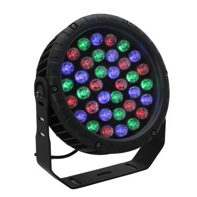
Flood using TIR lenses and single-color LEDs
Next Up
OK, this discussion of LED optics might have been a little bit dry. The next article, Part 3: Lighting Techniques, will provide more practical and useful information about using LEDs (and optics!) to achieve some captivating lighting effects.

2 thoughts on “LEDs for Light Art – Part 2: Optics”