
This article describes a variety of lighting techniques that can be used to achieve captivating and beautiful effects , employing the LED types summarized in Part 1 and the optical elements covered in Part 2 of this series. .

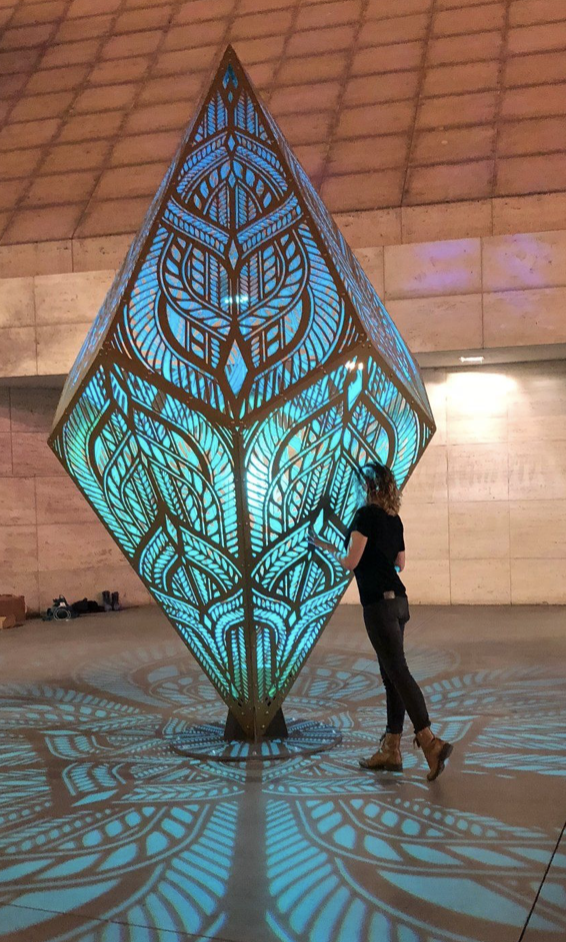
Squared, Charles Gadeken 
Iceberg, ATOMIC3
Introduction
Some new terminology will be helpful in categorizing the different lighting techniques discussed in this article.
Direct-view lighting: Light is emitted from the surface or interior of the artwork such that the majority of the light passes directly from the light source (and associated inline optics) to the viewer’s eyes. The majority of art that is considered “light art” relies heavily on this type of lighting.
Reflected-view lighting: Light is emitted from a source that is external to (but possibly attached to) the artwork, and is reflected off the artwork surface toward the viewer’s eyes. In some cases this type of lighting is an intrinsic part of the artwork, especially if it was part of the artist’s original vision. More commonly, reflected-view lighting is added afterwards, often as directed by the artist to enhance the impact of the art in a specific context or venue.
Yes, I completely made up this terminology, but hopefully you’ll find it useful. Note that the line between these two categories of lighting can be a little bit…blurry 😉.
Direct-View Lighting
Edge Outlining
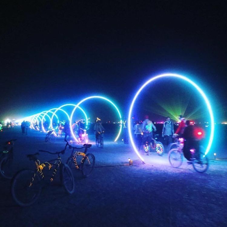
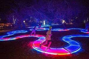
Edge outlining employs LED strips or strings (see Part 1) to outline an edge or perimeter of an artwork. The LEDs are usually covered by or enclosed in a diffuser (see Part 2) to achieve the appearance of a continuous line or arc of colored light.
Addressable LED strips/strings are often used to enable animated effects, even as simple as causing color changes to “flow” along the edge. However, non-addressable LEDs can also be used, including strips that are designed to simulate the appearance of neon light tubing.
Backlighting (Surface)
Backlit surface lighting involves the placement of LEDs behind a light-diffusive surface material with the intent of achieving uniform light intensity across the surface. Part 2 described the geometric requirements to achieve uniform intensity for a diffused LED strip, but this approach can easily be extended to 2-dimensional surfaces.
The diffusive surface material can be acrylic diffuser material, textured glass, epoxy resin, fabric, paper, or even a photograph printed on a translucent substrate. Additionally, patterned templates can be placed immediately behind or in from of the surface to create a silhouette effect.
In situations where the each discrete surface is to be illuminated with a single color (at any given time), non-addressable “analog” LED strips or modules can be used. Addressable LED strips can be used to create animated effects, for example, a “ripple” effect to simulate moving water.
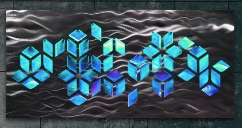
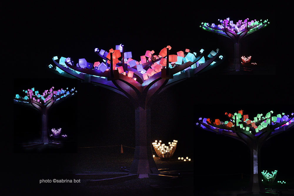
Backlighting (Volume)
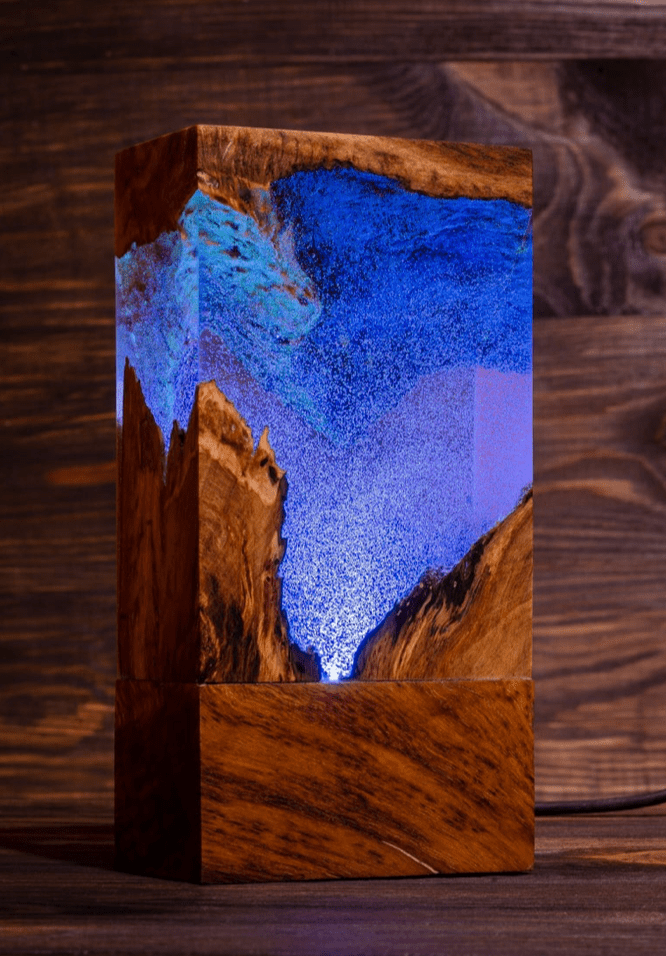
This is just the 3-dimensional extension of the 2-D surface backlighting technique. The volume can consist of replicated primitive shapes (cubes, spheres, cylinders) that form key components of the artwork, or can be the entire artwork itself. The use of molded/machined epoxy resin provides the freedom to use arbitrary shapes.
A challenge with this technique is to achieve uniform light intensity in all viewing directions. Since LEDs are inherently one-sided, this may require a customized mounting method, such as a custom printed circuit board, to achieve the desired LED orientations.
Edge Lighting
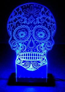
Edge lighting is applicable to situations in which it’s necessary to illuminate a surface, but there’s either not enough room to use back lighting, or it’s necessary for the surface to be transparent. This technique involves “injecting” bright light into one or more polished edges of a transparent material like glass or acrylic sheet. Optical discontinuities that are introduced into the material act to reflect and refract light beams outward toward the viewer’s eyes.
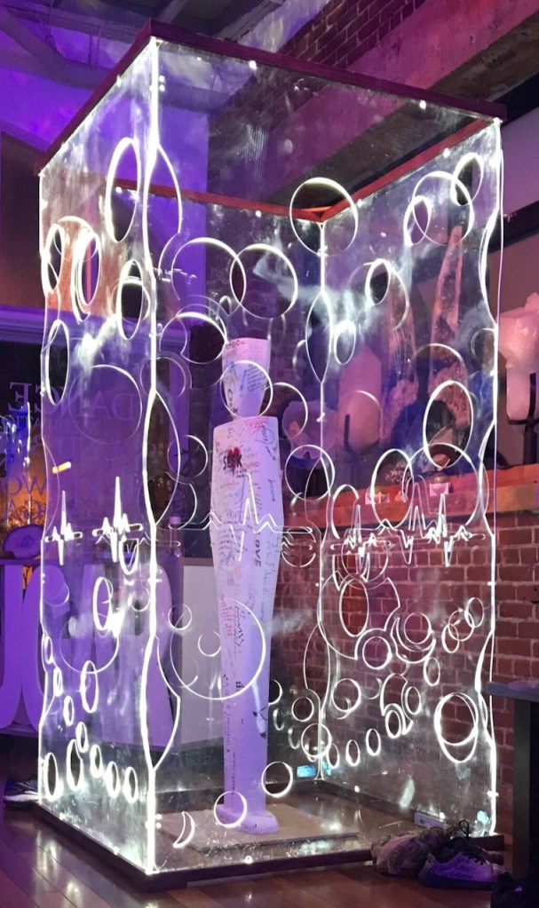
There are three common methods to create these optical discontinuities:
- Etch patterns into the front or back surface of the material using a laser etcher or CNC milling machine, as illustrated in the photo above right.
- Cut openings in the material, as illustrated in the photo to the right.
- Use a special type of acrylic sheet that is designed for edge-lighting applications. This material contains tiny diffuser particles that redirect light beams toward the material faces, while maintaining a very high level of transparency. The manufacturer Acrylite makes a product (formerly) called EndLighten that is ideal for this technique.
Obviously, LED strips are the perfect light source for this technique, since the strips can be mounted with the LED lenses pressed directly against the edge of any substrate that is thicker than the lens diameter, about 0.16″ (4mm).
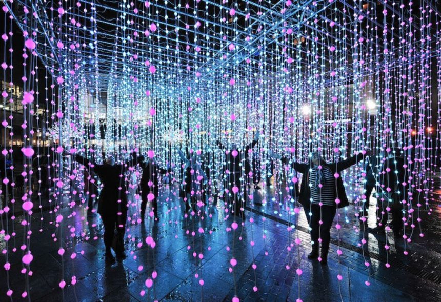
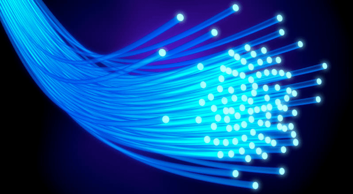
Fiber Optics
Flexible optical fiber can be used to couple light from an LED source to locations on the surface of an artwork that is not amenable to the electrical wiring that would be required for discrete LEDs or LED strips. Inexpensive plastic optical fiber (POF) is available in a range of diameters from 0.01″ (0.25mm) to more than 0.39″ (10mm). Depending on the type of outer cladding applied to the fiber core, fiber optic material can be manufactured in two varieties:
- End-emitting (or end glow) fiber is designed so that the majority of the light is transmitted (via total internal reflection) from the light source to the far end of the fiber, which appears as a bright point of light.
- Side-emitting (or side glow) fiber is designed to release light along the entire length of the fiber. The brightness of the side-emitted light decreases with distance from the emitter.
While an individual end-emitting fiber can be used to couple light from a single LED light source, it is more common to inject light from a single LED into a bundle of fibers, with each fiber then being routed to a different location on the art. If the latter method is used with an RGB LED, care must be given to the optical coupling between the LED and the fiber bundle. Due to the physical separation of the red/green/blue LEDs within the device, there is a possibility that each individual fiber will “see” significantly different luminous intensity from each of the color LEDs, resulting in color mismatch at the far ends of the fibers.
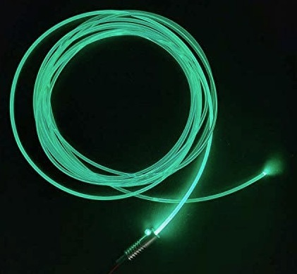
Side-emitting fiber can provide sufficient brightness even with a low-power LED, over distances up to about 5 feet (1.5 meters), in low ambient light conditions. Since much of the injected light reaches the far end, brightness and uniformity can be improved by covering the end with reflective mylar tape. Even better, light can be injected by a separate light source at each end. Increased brightness and distance can be achieved using the high-power LEDs described in Part 1, and also by polishing the illuminated end (face) of the fiber. Note that the metal “illuminator” in the photo above serves two functions: to capture and position the fiber end directly in front of the LED lens, and also to serve as a heat sink for the relatively high-power LED.
Reflected-View Lighting
Unlike direct-view lighting, the design of reflected-view lighting for art applications can steal many lessons from the world of architectural and landscape lighting. A Google search for some of the terms defined below will produce many useful results.
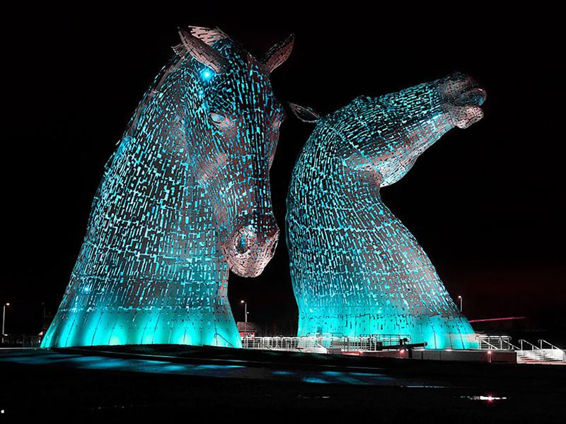
Flood Lighting
As the name implies, flood lighting uses external, high-intensity light sources to “flood” a broad area of an art piece with white or colored light. Multiple flood lights are needed to adequately illuminate a 3-dimensional piece with many facets that can be viewed from multiple perspectives. In contrast with the techniques described below, flood lights for a large art piece are typically mounted at a significant distance, at least 10 feet (3 meters) away.
If the art is interactive, or invites close-up viewing, a downside of flood lighting is that viewers passing in front of the lights will cast shadows. This can be partially alleviated by mounting the lights on towers instead of at ground level. But in both cases, underground or otherwise-protected wiring will be needed between the lights and the lighting controller.
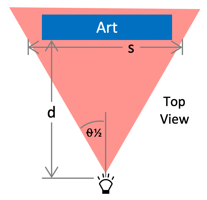
Most of the flood lights that are useful for art applications have a full-width beam angle (see Part 2) of between 20º and 60º. The optimal placement of a flood light should take into account both the beam angle (⍬) of the fixture and the distance (d) between the fixture and the face of the art to be illuminated. The diagram at right illustrates the top view of the horizontal beam spread (s) when a flood light is centered on the illuminated face. The distance (d) should be chosen so that the beam spread is just slightly greater than the width of the face, to avoid “wasting” light power. This relationship is determined by the formula:
d > s / (2 • tan(⍬½))For example, to compute the minimum distance to place a fixture with ⍬ = 40º to illuminate a 10 foot (3 meter) wide surface:
d > s / (2 • tan(40)) or
d > s / 0.84 or
d > 11.9 feet (3.6 meters)
Wall Wash/Graze Lighting
The wall wash technique is really just a special case of flood lighting, where a flat, vertical surface is to be uniformly illuminated by multiple lights sources that are mounted relatively close to the “wall”. Typical mounting distance from the wall is 12 – 36 inches (0.3 – 0.9 meters), and the lights can be mounted either on the ground or at the top of the wall on perpendicular brackets. The lights are angled significantly upward (or downward) so that the beam angle of each light encompasses the entire height of the wall (or nearly so).
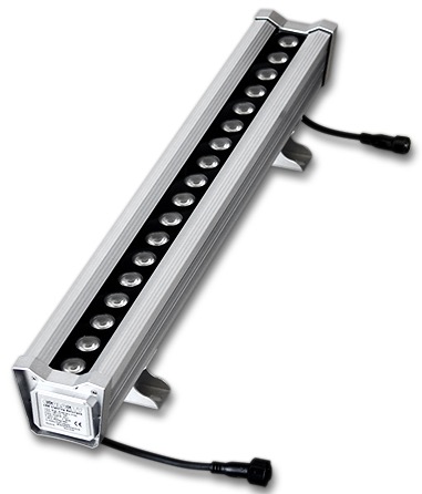
Multiple lights are mounted horizontally, spaced close enough together to avoid a “scalloping” effect near the base of the wall. An alternative is to use a specialized wall wash light fixture, an example of which is shown above.
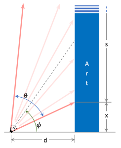
The diagram at right is a truncated side view of a light source with beam angle ⍬ illuminating a flat vertical surface at a distance d from the light. The central axis of the light is pointed upward at angle 𝜙, and the total beam spread at the face of the wall is distance s.
Due the limited number of options available for the fixture beam spread, a compromise may be required in aiming the fixture so that the beam spread reaches the top of the wall. Depending on the mounting distance d, the beam may not fully illuminate the bottom of the wall (distance x) as illustrated in the diagram. One solution is to move the fixture closer and slightly increase the pointing angle 𝜙, but this can have negative side effects, as discussed below.
Because you’re dying of curiosity about this, here are the equations:
s = d • (tan(𝜙 + ⍬½) - tan(𝜙 - ⍬½))
x = d • tan(𝜙 - ⍬½)
For example, illuminating a 20 foot (6.1 m) wall from a distance (d) of 2 feet (0.6 m) with beam angle ⍬ = 60º requires a pointing angle 𝜙 = 55º. This results in a non-illuminated distance (x) of only 11 inches (0.3 m). In reality this area will receive some light, since all light sources emit some light at angles slightly beyond the specified beam angle.
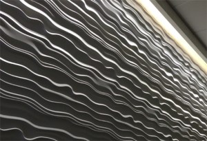
Just as wall wash lighting is a special case of flood lighting, wall graze lighting is an even more specialized technique in which the light source is extremely close to the wall, usually less than 1 foot (0.3 m) away. Unlike wall wash lighting, the goal here is to create shadows and lighting irregularities to emphasize the texture of the wall surface. Wall graze lighting is best accomplished with narrow beam-angle lights that are aimed nearly vertically.
Recessed/Silhouette Lighting
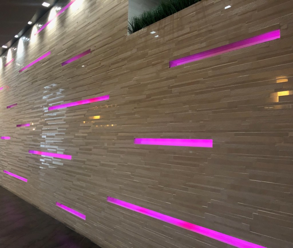
This somewhat specialized technique has three objectives: 1) to illuminate a surface that is recessed with respect to the front “face” of the artwork; 2) create a light intensity or color contrast between the recessed surface and the front surface (i.e. to silhouette the front face); and 3) to keep the light source hidden from view within the recessed space. Typically the depth of the recess is less than 2 feet (0.6 m), and the other dimensions are such that hidden light sources mounted around the edges can reach all points on the the recessed surface.
For recessed surfaces in the shape of elongated rectangles (as in the photo above), LED strips are the obvious solution. LED strips can be mounted along one or both edges, with the mounting locations and pointing angles chosen to optimize light uniformity while keeping the LEDs hidden from view.
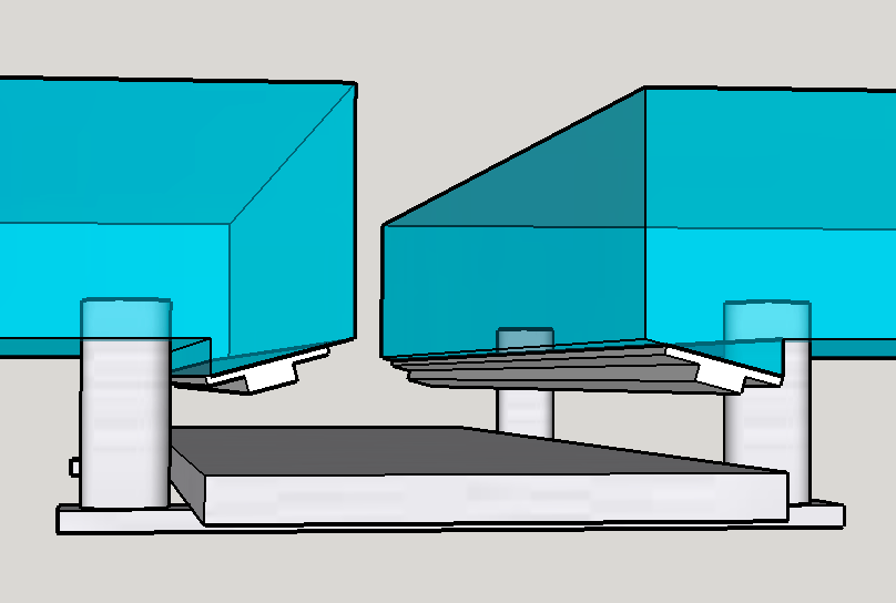
The two diagrams below show a recessed lighting concept for an art piece to be constructed from thick translucent glass blocks held in place by stainless steel bars. The artist wanted to highlight the stainless steel elements with bright light, relying only on ambient light to backlight the glass to a lesser degree. To accomplish this effect, non-addressable RGBW strips are mounted on the backside of each glass block, angled slightly inward.

Next Up
Congratulations! You made it to the end…except for Part 4, which will discuss hardware circuits used to drive various types of LEDs.

2 thoughts on “LEDs for Light Art – Part 3: Lighting Techniques”