This article describes hardware circuits, as part of a microcontroller-based lighting control system, that can be used to reliably and efficiently drive the various types of LEDs described in Part 1.


Introduction
This article starts with the basics of driving a single LED in a constant-voltage or constant-current mode, and then explores the options to achieve per-color dimming control using pulse-width modulation (PWM). Next is a discussion of techniques to drive both analog and digital/addressable LED strips, addressing both the color data/control signals and the challenges of distributing power to long runs of LED strip.
Constant-Voltage Drivers

The brightness (luminous flux) of an LED depends primarily on the amount of current flowing through the device in the forward direction, referred to as If. LED manufacturers provide a specification for the “typical” If value at which the LED is designed to be operated continuously. The forward voltage drop (Vf) across the device, when operating at the rated If, can vary significantly depending on temperature and lot-to-lot manufacturing variations. As shown in the example diagram at right, If rises sharply as Vf is increased, but there is some uncertainty about the exact correlation between Vf and If without more detailed analysis of the specific LED and the operating conditions such as ambient temperature.
Why is this important? Because it is tempting to drive LEDs with a very simple circuit that uses a fixed (constant) voltage power supply, and that only indirectly controls the current through the LED. While this can work, careful analysis and component value selection is required to achieve a circuit with good performance and long-term reliability.

The diagram at right shows a typical constant-voltage LED driver circuit. A power supply (not shown) provides voltage Vps, causing current to flow through the LED and a series “current-limiting” resistor when the MOSFET is switched “on” to provide a low-resistance path to ground. The resistor value R is selected to drop the voltage difference between Vps and Vf while setting If at the LED’s rated operating current, using the formula:
R = (Vps - Vf) / If
Due to the uncertainty in the actual value of Vf, it’s important to use the minimum possible value in the formula above. Since the LED Vf actually falls as temperature rises, this approach ensures that If cannot exceed the rated value even under extreme operating conditions. The drawback of this conservatism is that If (and brightness) will be less than the rated value at lower temperatures.
Another related tradeoff is the selection of the power supply voltage Vps. Using a relatively low voltage (like 5 volts) relative to Vf minimizes power dissipation in the resistor, but also increases the sensitivity of If (as a % of nominal) to changes in Vf. Conversely, using a higher voltage like 12V significantly reduces the sensitivity to Vf changes, but can result in the need for a high-power resistor (which will get hot!). The formula for power dissipation in the current-limiting resistor is:
P = (Vps - Vf)2 / R) or P = (If)2 • R 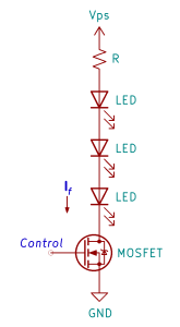
For example, driving a high-power LED with rated If = 350mA using a 12V power supply would require a 5W current-limiting resistor! That’s one reason why the use of constant-voltage drivers is typically limited to lower-power LEDs. In some situations it’s possible to reduce resistor power dissipation by driving multiple LEDs with the same circuit, as illustrated at right. This works as long as the sum of the Vf for all of the LEDs is less than Vps, but has the downside of preventing individual control of each LED.
As mentioned above, the N-channel MOSFET is operated as a 2-state switch that is either fully off (very high resistance) or fully on (less than 1Ω resistance), based on the control signal applied to the gate pin. This type of application typically uses a logic level MOSFET that can be directly controlled by a microcontroller digital output signal. Many specific MOSFET types are available, including ones that are compatible with either 5V or 3.3V logic levels.
While constant-voltage LED driver circuits can be incorporated into a custom printed circuit board design, it’s also possible to construct these using small and inexpensive MOSFET driver modules that are available from Amazon and DIY suppliers.
Constant-Current Drivers

A constant-current LED driver is based on a buck converter circuit, which is essentially a variant of a step-down switch-mode power supply. It’s pretty simple at a “black box” level, as shown in the diagram at right. It accepts a fixed-voltage power supply (Vps) and a control input, and drives one or more LEDs wired in series. The selection of components within the driver circuit sets the desired LED current (If). The circuit continuously senses the actual current level and rapidly adjusts the applied voltage to maintain the desired current regardless of changes to LED Vf or other factors. Due to the efficient switching technique used, the driver circuit itself typically consumes less than 20% of the LED power consumption, and can be as low as 2-5%. The only requirement is that the supply voltage be at least a few volts higher than the sum of the forward voltages (Vf) of the LEDs being driven.
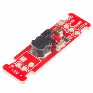
Constant-current (CC) drivers can be used with any type of discrete LED, but they are most valuable in achieving optimal performance with high-power LEDs across a wide temperature range. While a CC driver contains only a small handful of components, the details of the circuit are beyond the scope of this article. Fortunately, schematics are easy to find online. Even better, inexpensive CC driver modules can be purchased from multiple sources, such as the one shown here from Sparkfun. This module can drive up to 1A of LED current, and is available in a 3-channel version for RGB applications.
The Control input to a CC driver can be used two different ways to achieve on/off or dimming control of the LED. In the first mode, the Control input accepts an analog voltage (with a range of several volts) that determines the LED current as a percentage of the set point defined by the circuit. For the module shown above, varying the control input in the range 0.5 – 2.5V will cause the LED If to vary between 20- 100% of the set point (defined by jumpers and circuit component values). Partly because the current (and brightness) cannot be adjusted all the way down to 0, this mode is not recommended for applications that require color mixing across the full range of RGB values.
In the second dimming control mode, the Control input is a digital signal that enables or disables the driver circuit. When the input is high (> 2.4V) the driver applies the full set point current to the LED. When the input is off (< 0.4V) the driver is disabled and current to the LED is shut off. Different LED brightness levels, based on the average LED current, are achieved by imposing a pulse-width modulation (PWM) waveform on the Control signal, as described further in the next section.
PWM Dimming Control
Pulse-width modulation (PWM) can be used to achieve LED brightness control (i.e. dimming) with both the constant-voltage and constant-current driver circuits described above. LED luminous flux (perceived as relative brightness) is proportional to forward current If. Due to the finite response times of both LEDs and human eyes, it is the average current that determines perceived brightness, under the condition that the LED current is toggled between full-on and full-off at a high enough frequency. For most light art applications, a toggle frequency (i.e. the PWM frequency) between 300 Hz and 1 KHz is high enough to prevent noticeable flicker while minimizing switching losses (i.e. heat) caused when MOSFETs switch between the on and off state.

The LED average current is determined by the ratio of the on/off times of the LED current during each PWM cycle. This is referred to to as the PWM duty cycle, as illustrated in the diagram.
Most microcontroller unit (MCU) designs contain one or more dedicated counter/timer units that can be used to generate PWM signals on associated general-purpose digital outputs. With an MCU supporting the Arduino programming framework, the duty cycle of these PWM outputs can be easily changed by using a standard library function: analogWrite(). For most MCUs, the resolution of the PWM duty cycle is 8 bits, meaning that that there are 28 = 256 different PWM duty cycle values are available to control LED brightness. When three PWM signals are used are used to control the individual colors of an RGB LED, the total number of brightness combinations (i.e. the number of different possible colors) is 2563 = 16,777,216. Millions of colors!
There are two possible downside to using an MCU’s “built-in” PWM outputs for LED dimming control. The first possible issue is that the MCU may not have enough PWM outputs to support the application. Some MCUs have only a handful of PWM outputs while others may have as many as 30. But since most MCU I/O pins have multiple functions, you may not be able to use all of the “PWM-capable” pins if they’re needed for something else in your design.
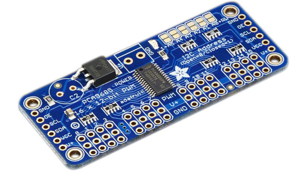
The second downside is that 8-bit PWM resolution isn’t adequate for certain types of dynamic effects, especially color fades at low brightness levels. The human eye is very sensitive to low-level brightness changes, so a sequence that slowly increases the brightness of an LED from off to full brightness may appear choppy, at least at the start of the effect. One solution is to use an external PWM driver chip that supports 12- or 16-bit PWM duty cycle resolution. An example of this type of chip is the PCA9685, which provides 16 PWM channels each with 12-bit resolution. An I2C bus provides a simple interface to the MCU. The PCA9685 chip can be incorporated into a custom circuit board design, but is also available as a module as shown above.
As mentioned earlier, a PWM signal from either an MCU or an external PWM chip can be used to directly control either a constant-voltage or constant-current LED driver.
Analog LED Strip Driver
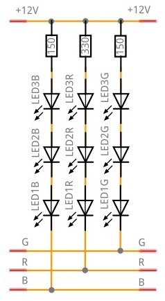
As described in Part 1, analog (non-addressable) RGB LED strips are built using the multi-LED, constant-voltage configuration shown at right. Each group of 3 adjacent LEDs on the strip share a set of 3 current-limiting resistors, one for each color. The cathodes of each color all the LEDs on the strip are tied together, so that three MOSFETs can provide dimming control for the entire strip (see the section above on constant-voltage drivers).
The typical If current rating for a 5050 LED is 20mA. The total amount of current that will flow through the per-color dimming MOSFET is:
IFET = If • (N / 3)where N is the number of 5050 LED modules on the strip. For example, a 5m section of 60 LED/m strip has 300 LEDs. The MOSFET current (when on) is therefore IFET = 0.02 • (300 / 3) = 2A. That’s well within the capabilities of very inexpensive devices in small SMT packages.
Digital LED Strip Driver
The LED modules used in digital (addressable) RGB LED strips contain some of the circuits previously described in this article. In particular, they contain per-color constant-current drivers and PWM controllers (usually with 8-bit resolution). So all that’s needed to drive these strips is a power supply (usually 5v or 12v) and a single data signal that contains the 24-bit color data for each addressable RGB LED. Some types of strips also use a clock signal, but the net effect is the same.
So..super simple, except when it’s not! There are a couple of scenarios in which some additional circuitry is needed. First, the data (and clock) signals used by most strips operate using 5v CMOS logic levels, where the “high” logic level requires a voltage of at least 3.5v. This level can’t be achieved by the outputs from an MCU that operates from a 3.3v power supply. Since 3.3v MCUs are becoming increasingly common, there is a growing need to include a “logic level shifter” circuit between the MCU digital output and the data input (DIN) of the LED strip. During initial testing, some strips may operate correctly without a level shifter circuit, but long-term reliability cannot be guaranteed, especially across a wide temperature range. There are many options available to implement a logic level shifter circuit, and again this circuit can be implemented using discrete components or an off-the-shelf module. This article discusses level shifters in much more detail.
The second scenario arises when the “input” end of the LED strip is located a significant distance (more than 10 feet or 3 meters) from the controller. The resistance and parasitic capacitance of the wire carrying the data signal will act to degrade the amplitude and shape of the signal waveform, to the point where the first LED on the strip will not be able to correctly receive and interpret the signal. This may result in erratic operation or no functionality at all for the entire strip.
There are three options available to mitigate this issue:
- Add a circuit to the data signal (on the controller) that is designed to drive a signal across a long cable while maintaining the desired waveform shape. Numerous line-driver chips and related circuit designs are available for this purpose. In this simplest case, this could just be a low value resistor (33 – 100Ω) in series with the data signal that damps reflections returned from the far end of the cable (this is recommended even for short cables).
- Add an external “signal repeater” module inline with the cable between the controller and LED strip. Many such modules are available online, and they basically provide the same type of line-driver circuit described in #1 above. An inexpensive approach is to use an individual LED module (like the WS2812b or WS2815), inserted in the middle of the cable run, as a line-repeater/driver. The data signal received on the DI input is re-shaped and then independently driven on the DO output. Note that individual LED modules can be purchased on their own tiny PC boards with connection pads, making this approach more feasible.
- Convert the data signal (on the controller) to a differential signal, and add a circuit board containing a differential receiver at the far end of the cable (near the LED strip input). There are many ways to do this, but the easiest may be to use components intended for implementing an RS-422 differential serial interface. This approach allows for extremely long cable runs. And…one more time: off-the-shelf RS-422 modules are available to implement the transmitter and receiver functions.
LED Strip Power Injection
No discussion of LED strip drive methods would be complete without a discussion of “power injection”, a technique to mitigate the voltage drop that occurs across long runs of LED strip caused by high current levels flowing through the thin copper traces of the strip substrate. Excessive voltage drop can cause erratic operation or brightness/color shifts along the length of the strip. The diagram below is a bit busy, but it’s helpful in illustrating what’s going on in the power distribution system for an LED strip.

Imagine a hypothetical 3-module addressable LED strip with a power supply voltage Vps. Each of the wires from the power supply and ground connections has a resistance of Rw, which depends primarily on the gauge of wire used (see this wire gauge resistance table). The copper traces within the LED strip also have resistance, and the resistance of the trace segments between adjacent LEDs is represented as Rs. Assuming that all LEDs are on a maximum brightness (R+G+B = White), the same current Im flows through each module. But because all of the modules share the same power/ground traces, the first segment of the power/ground traces carry three times the current carried by the last segment.
The voltage at the positive terminal of each of the modules (Vp1, Vp2, Vp3) is reduced relative to Vps by the I•R voltage drops across the resistances between the module and the power supply. So while it might be a bit challenging to compute exactly, it’s clear that the voltage will be lowest at the last module on the strip (Vp3).
It’s very important to realize that exactly the same thing is happening on the ground traces, except in the opposite sense. The I•R voltage drops act to increase the voltage at the modules’ ground terminals relative to ground. So the actual supply voltage “seen” by module 3 is Vm3 = (Vp3 – Vg3).
Fortunately, the modules used in addressable LED strips, which contain constant-current drivers, have some tolerance in the operating voltage range. For example, the WS2815 LED module has a specified voltage range of 9.5 – 13.5v. The data sheet doesn’t clarify whether full performance is maintained at the lowest supply voltage, so it’s probably safer to use 10 – 10.5v as a target minimum when assessing voltage drop.
The basic approach to mitigate voltage drop is to minimize the resistance of the paths by which current flows between the power supply and each of the modules (in both directions!). The easiest method is to use heavier-gauge wire between the power supply and the strip, reducing Rw in both power supply wires. But this often isn’t adequate when multiple strips are daisy-chained together.

As a next step, additional current paths are provided by running one or more extra sets of power/ground wires to remote points along the strip and/or at the end. While these additional wires also have resistance, since they are wired in parallel with the baseline resistance, the net resistance between all modules and the power supply is reduced. This approach, illustrated at right, is often referred to somewhat inaccurately as “power injection”.
In practice, experimentation is usually required to determine the wire gauge required and the best attachment points for the additional power wires. This will also depend heavily on the specific type of LED strip as well as the colors and brightness levels used.

Great read!
A few other resources (Adafruit to name one) are suggesting adding a 1000uf Cap at the beginning of an addressable led strip however there isn’t really a neat/logical explanation for necessity of this cap anywhere on the internet. Would you be able to comment on this?
LikeLike
Sorry! Looks like I never got around to responding. I think the correct answer to this questions is: It depends 😉
A large capacitor across the power supply output (usually 5V or 12V) is intended to reduce the magnitude of a voltage droop caused when a large number of LEDs are turned on simultaneously (e.g. off to full-brightness white). A good quality power supply will be able to respond very quickly to transient changes in current demand, minimizing the voltage droop, partly because the power supply itself contains one or more “large” capacitors (although maybe not 1000µF). Adding more capacitance close to the LED strip input doesn’t hurt, but is probably unnecessary unless you’re using a really crappy power supply or are driving a huge number of LEDs (that get turned on simultaneously).
LikeLike
hello, what will happen when one of the string fails to operate connected across CC driver, will it transmit the current to remaining ?
LikeLike
Hi! Could you please clarify your question? I can’t tell if you’re asking about a CC driver with discrete LEDs, or an addressable LED strip in which each of the LED modules contains a CC driver circuit. In the later case, a failure of one module in the strip will usually prevent the data signal from reaching the following LED modules in the strip, and they won’t light up at all. The exception is with strips like the WS2813 and WS2815, which use a redundant (backup) data signal to bypass failed modules and allow the remaining LEDs to operate correctly.
LikeLike
Very useful series of articles! Thanks!
LikeLike