
The goal of this article is to give you all the information you need to design the wiring for a project that includes one or more addressable LED strips. And you’re thinking: “Does the world really need another article explaining power injection?” Well, yes, but only if you’re not satisfied with generic “rules of thumb” and want to really understand what’s going on.
And then: “Whaat? Wiring needs to be designed?” Yeah, as you’ll see below, there are many options and technical tradeoffs to consider, and decisions to be made, and that’s what design is all about. This article will cover the initial phase of wiring design, focusing primarily on the wire itself. Subsequent articles will cover related topics (like connectors) that will help you achieve long-term reliability and performance, especially when your project will be located outdoors.
Overview
In most situations, your addressable LED controller and power supply will be located some distance away from the input end of the LED strips. You’ll need to choose a type of interconnect cable that meets these goals:
- Easy to route and connect to the controller, power supply, and LED strips
- Durable
- Carries the required amount of current while minimizing the amount of voltage drop that occurs in the cable (which can cause the LEDs to malfunction)
- Eliminates any risk of overheating and fire
This article will help you find the lowest-cost solution for your project that meets these goals. Most of the discussion focuses on providing power to the LED strips, since that’s the primary factor in the selection of appropriate cabling. While in theory the LED strip data signal could be carried in a separate (smaller) cable, it’s usually more convenient to carry the data signal in the same 3-conductor cable as the power and ground connections. Basically, the data signal will be perfectly happy with whatever cable you choose to optimize the power connections. But the details of the circuit that produces the data signal in the controller are very important in achieving optimal performance and reliability. These details are discussed in this article.
Wire Types
Copper is the most commonly used conductive material used to fabricate electrical wire (single conductor) and cable (multiple conductors). Many cable manufacturers will tout their products as using oxygen-free copper (OFC), although the advantages in LED lighting applications are minimal. At best, OFC may be less susceptible to long-term corrosion if a bare (non-insulated) section of wire is exposed to air. On the other hand, manufacturers like to highlight their use of OFC to distinguish their products from competitors that may use lower-cost copper-clad aluminum (CCA) conductors. While CCA has some valid applications, its much lower conductivity (i.e. higher electrical resistance) pretty much precludes its use in lighting applications.
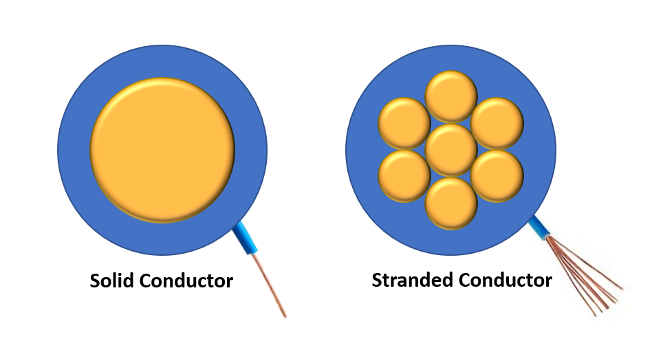
Single-conductor, insulated copper wire is typically manufactured in either a solid or stranded configuration. Solid wire consists of a single strand of round cross-section wire encapsulated within an insulating sleeve. Stranded wire contains multiple strands within the same insulator. For lighting applications, a solid wire and a stranded wire of the same wire gauge (more on this below) will have essentially identical electrical properties. [But this isn’t true for all applications, especially those involving very high-frequency signals].
Stranded wire is generally much more flexible than solid wire. and the flexibility of the wire increases with a higher number of strands. There is no standard for the number of strands, but it will usually be listed in the wire specifications. The minimum number of strands is 7, but wire specifically designed for high flexibility can have more than 100 strands.

Stranded wire (but not solid wire) is often tinned, meaning that each strand is coated with a thin layer of solder, giving it a silvery color. This protects the wire from oxidation and corrosion, and also makes it easier to solder. You can convince yourself that it’s really copper underneath by scraping off a bit of the tinning with a sharp knife.
Given the advantages of stranded wire, why would you even consider solid wire? Three reasons:
- It’s sometimes easier to find solid wire/cable that is specifically intended for outdoor applications, that is resistant to water and UV exposure and can be buried underground without a protective conduit. I’ll cover this more in a future article.
- Solid wire is easier to attach to certain types of connectors, including push-in and screw terminal blocks. Stranded wire often requires a ferrule.
- For some applications, solid wire is preferred because it retains its shape when bent. Stranded wire usually needs to be restrained with zip ties or adhesive.
Wire Gauge
Gauge refers to the diameter of a solid wire with a round cross-section. For the types of wire discussed in this article, the American Wire Gauge (AWG) is the most commonly-used wire gauge measurement system. IEC 60228 is a less commonly-used metric standard.

The AWG system is somewhat non-intuitive, in that the AWG value of a wire increases as the diameter of the wire decreases. For addressable LED lighting, the most commonly used AWG sizes are 14 (largest), 16, 18, 20, and 22 (smallest).
But what about stranded wire? Well, it turns out that diameter isn’t a useful measurement for stranded wire, since there are tiny air gaps between the individual strands that don’t contribute to electrical conductivity. So instead, the total cross-sectional area of the copper in a stranded wire is computed and compared to the area of a solid wire with a specified AWG. For example, the total copper cross-sectional area of a stranded 20 AWG wire will be the same as a solid 20 AWG wire, but the diameter of the stranded wire will be larger due to the internal air gaps. That’s why stranded and solid wire of the same AWG have approximately the same electrical conductivity. [Note that many websites get this point wrong].

Insulation
Just a few points about insulation, and I’ll save the rest for a future article about weatherproofing.
Flexible Polyvinyl Chloride (PVC) is the most commonly-used material for both wire insulators and cable jackets. It is resistant to flame, moisture and abrasion, and remains flexible over a wide temperature range. Silicone insulation is also used in cables designed for high flexibility.
Although wire/cable manufacturers will typically specify the type of insulation used, the actual properties can vary widely. For example, the ease of stripping individual wires and the cable jacket can range from super-easy to maddeningly difficult. Heat shrinkage can also be an issue. When soldering some types of PVC-insulated wire, the insulation softens and shrinks away from the solder joint, leaving too much bare wire exposed. I highly recommend buying and testing a sample of wire/cable before committing to a large purchase.
Wire Resistance
OK, now we’re getting to the good stuff!

As you hopefully already know, the electrical resistance of a wire is a measure of the degree to which the wire impedes the flow of electricity. The unit of measure is the Ohm (Ω) and when discussing variable-length wiring it’s convenient to specify the resistance per unit length (meter or foot). The table at right shows the unit-length resistance of common wire gauges, and applies to both solid and stranded wire. Note that wire resistance increases with temperature. In the case of copper wire, the values shown in the table will increase by 0.39% for every 1 ˚C rise in temperature.

The phrase “impedes the flow of electricity” means that when a signal with voltage Vin is applied to a wire, the voltage will be lower when it reaches the end of the wire. The amount of voltage drop depends on two things. The first factor is the total resistance of the wire (Rwire), which can be computed from the table above. The second factor is the amount of current flowing through the wire (Iwire). The total voltage drop across the wire can be computed using Ohm’s Law:
Vdrop = (Vin – Vout) = (Iwire) x (Rwire)
Here’s an example: Let’s say you have a 12V LED strip that requires a maximum current of 3.6A, and you want to use a 3 meter 20 AWG cable:
Rwire = 3 meters x 0.033 Ω/m (from table) = 0.1Ω
Vin = 12V
Vdrop = 3.6A x 0.1Ω = 0.36V
Vout = Vin – Vdrop = 12V – 0.36V = 11.64V
So how much voltage drop is acceptable? If the voltage drop across the wire is large, the voltage received by the LED strip may be too low for it to operate correctly. But we need to cover a few more topics before we can quantify this.
LED Strip Power Consumption
The majority of LED strips require a DC power supply of either 24V, 12V, or 5V, although addressable strips typically use 12V or 5V. But regardless of the voltage used, most of the LEDs used in strips require roughly the same amount of power to produce an equivalent amount of light. Since power is the product of voltage x current, that means that a 5V LED strips requires 12 / 5 = 2.4 times more current than a 12V strip. As discussed above, higher current results in more voltage drop, which can cause problems unless a more expensive, heavier-gauge wire is used to reduce the resistance. That means that, from a wiring perspective, there is a significant advantage in using higher-voltage LED strips.
The actual amount of power required by an LED strip depends on multiple factors, and it’s difficult (and perhaps dangerous) to generate or use generic “rules of thumb”. The LED module technology used in LED strips is continually improved, but specification changes are not clearly communicated by LED strip vendors.
For example, you’ll find many, many website and posts that confidently state that the power consumption of a single WS2812b module at full-brightness white (R+G+B) is 0.3W. Since this is a 5V device, this translates to a total current draw of 0.3W / 5V = 0.06A or 60mA. Well, this was true for very old versions of the WS2812b, but for the current version (WS2812b-V5) the full-brightness white current is only 0.18W, or 36mA. That’s a huge difference when there’s a large number of LEDs involved!
This brings up a good point. It’s very common to “size” the wiring and the power supply based on the maximum current that the LED strips may require under any circumstances, including setting every single pixel to full-brightness white. But if you know with certainty that your animation software will never generate this condition, you can use a different set of assumptions to determine the worst-case maximum current for your project. Just be sure, to avoid the chance of melting your wiring or even starting a fire!
The bottom line here is that you need to carefully examine the specifications of the exact LED strips that you intend to use, to determine the maximum power (or current) per module. But LED strip vendors are notoriously bad at providing this information, and even when they do it is often incorrect. You may be better off buying a sample and measuring the power consumption yourself, keeping in mind that power consumption varies with temperature and may not be exactly the same for strips of the same type from different manufacturing runs. For those reasons it’s a good idea to include a sizable “safety margin” when selecting wire gauge and power supplies.
For my own projects, I almost always use 12V WS2815 LED strips, both because of the higher voltage and the provision of a backup data signal. The backup data signal prevents a single module failure from taking out the whole strip, and is a great feature when reliability is important. One oddity of these strips is that the per-module power consumption varies only with the brightness, not with the number of RGB channels used. The maximum per-module power consumption is specified as 0.18W (15mA) regardless of what combination of the R, G, or B channels are turned on. [My measurements are closer to 12mA at room temperature].
Note that the per-module, full-brightness-white power specifications for the WS2815 and WS2815b-V5 are identical: 0.18W. But the WS2812b-V5 requires 36mA while the WS2815 requires only 15mA. For larger projects that makes a big difference when it comes to wiring design!
Here’s video that provides a good overview of the various types of LED strips currently available, with an emphasis on power consumption.
At this point, you should have a good understanding of how to compute the maximum current (Iwire) that will flow through the wires connecting the power supply to your LED strip(s).
Voltage Drop Calculation
Two gold stars for making it this far! But now we need to dive in a bit deeper to really understand how voltage drop affects the operation of an LED strip. Here’s a more accurate representation of the connection between a power supply and an LED strip.

VPS is the output voltage of the power supply, as measured between the V+ and GND (ground) terminals. VLED is the voltage measured at the input of the LED strip. ILED is the worst-case maximum current drawn by the LED strip, and since this is a circuit, the current flowing into the LED strip on the V+ wire is exactly the same as the current flowing back to the power supply on the GND wire. Assuming that the same gauge wire is used for both connections, Rwire1 = Rwire2.
The key concept here is that voltage drop occurs on both the V+ connection and the GND connection. Since the currents are the same, and the wire resistance is the same, the magnitude of the voltage drop is the same on both connections. But since the current direction is opposite, the total voltage “seen” by the LED strip is reduced by twice the individual voltage drops. Mathematically speaking:
Vdrop(V+) = Vdrop(GND) = Vdrop = ILED x Rwire
V+(LED) = V+(PS) – Vdrop(V+)
VGND(LED) = VGND(PS) + Vdrop(GND) = 0V + Vdrop(GND) = Vdrop(GND)
VLED = V+(LED) – VGND(LED) = V+(PS) – Vdrop(V+) – Vdrop(GND) = V+(PS) – 2 x Vdrop
VLED = V+(PS) – 2 x (ILED x Rwire)
Crystal clear, right? OK, here’s a continuation of the previous example, where V(+)PS = 12V, ILED = 3.6A, and Rwire = 0.1Ω.
VLED = 12V – 2 x (3.6A x 0.1Ω) = 11.3V
But…we still don’t know quite enough to determine if this amount of voltage drop is acceptable.
Input Voltage Range
While addressable LED are typically specified as either “12V” or “5V”, they are actually designed to operate over a range of voltage. For example, the “12V” WS2815 LED module is specified to operate over a range of 9.5V to 13.5V. The “5V” WS2812b-V5 module operates over the range 3.7V to 5.3V. Unfortunately, the manufacturers don’t say what happens when the module’s input voltage approaches the low or high end of the range.
Exceeding the high end of the voltage range runs the risk of permanently damaging the LED modules, although there’s likely some conservatism in that spec. Driving the module with a voltage lower than the minimum spec (due to voltage drop in the wiring, for example) could result in reduced brightness or erratic performance (the dreaded “flickering problem”). But again, it’s likely that most manufacturers have added some margin to the minimum voltage spec (see below).
Note that most addressable LED modules employ internal current source (or current-mode) LED drivers that maintain the LED current at a desired level even when the input voltage varies within the specified operating range. That means that a well-designed LED strip will meet its brightness (luminous intensity) specifications over the full input voltage range. I did a quick test of a BTF-Lighting WS2815 strip, and couldn’t detect any change in brightness over the full 9.5V – 13.5V range. In fact, it continued to operate correctly (with animations running) down to 6V, with a barely-discernible reduction in brightness.
Back to the example: If VLED = 11.3V and the LED modules will operate correctly down to 9.5V, everything’s cool, right? Sorry to disappoint, but there’s yet another factor we have to consider.
LED Strip Voltage Drop
An LED strip is actually a long, skinny printed circuit board made with flexible materials. Printed copper traces provide the power, ground, and data connections to the LED modules mounted across the length of the strip.
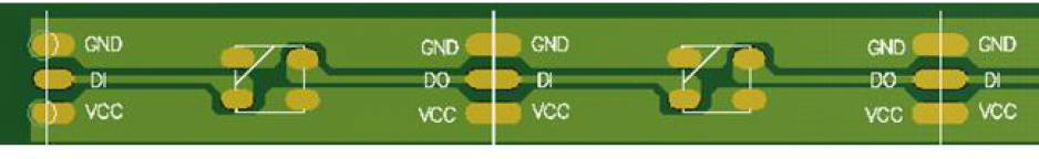
These copper traces are really just wires with a rectangular, rather than circular, cross section. And just like “normal” wires, PCB traces have resistance based on their cross-sectional area and length. The width of the traces is constrained by the total width of the strip, which is 12mm for most addressable strips. As shown in the drawing above, more of the width is dedicated to the power/ground traces that will be carrying high currents.
The key variable here is the thickness, or “weight” of the copper traces. Unfortunately, LED strip manufacturers rarely provide this important specification. But even if they did, it would still be difficult to compute the actual resistance of the traces, due to the trace width variations. And even if the actual trace resistance was known, the voltage drop along the length of the strip would be tough to calculate. The diagram below illustrates the challenge.
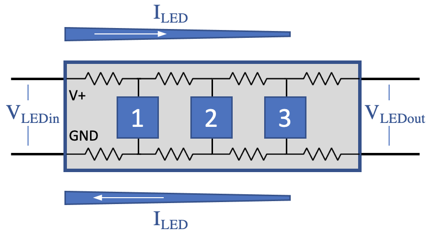
The internal copper traces are represented as a series of resistors, with each module tapping into the power/ground connections at their location. At the input end of the strip, the V+ trace carries all of the current for all of the LED modules. But between modules 1 and 2, the V+ traces carries all of the current except for that of module 1. By the end of the strip, the V+ trace is only carrying the current for module 3. What this means is that voltage drop is occurring within the strip, and that the voltage drop accumulates based on the length of the strip and the number of LED modules, but it’s not as simply as multiplying the per-segment resistance and the total strip current. I could give you the equations, but it’s kind of pointless given the difficulty of determining the trace resistance.
While the sections above show how to analytically determine the voltage drop that will occur in your wiring (up to the input of the LED strip), determining the additional voltage drop within the LED strip is best done empirically, with hand-on testing. Here’s a suggested approach:
- Get an LED strip of exactly the same type that will be used for your project. The length doesn’t need to be the same as the final configuration, as long as the actual length of the test strip is known. So the length of the test strip is Lengthtest and the length of the real strip is Lengthproj.
- Connect the LED strip to a power supply. The wiring isn’t important as long as the length/gauge will result in a “reasonable” voltage drop in the wiring (see more below).
- Connect the LED strip to your controller, and use it to send data that will turn on all pixels to full-brightness white (or whatever your expected worst-case condition is). Ether compute or measure the total LED strip current under these conditions (ILEDtest). Then extrapolate this to the expected current for your project strip: ILEDproj = ILEDtest x (Lengthproj / Lengthtest)
- Use a multimeter to measure the voltage across the V+ and GND pins at the input end of the test strip, VLEDin(test). Ensure that this voltage is within the specified operating range of the LED strip. If it’s too low, use beefier wiring, or (if possible) turn up the power supply voltage.
- Use a multimeter to measure the voltage across the V+ and GND pins at the output end of the test strip, VLEDout(test).
- The worst-case voltage drop within the LED test strip is then Vdrop(LED) = VLEDin(test) – VLEDout(test). Note that this measurement includes the voltage drop that occurs in both the V+ and GND traces.
- Use the length of the test strip to compute the LED strip voltage drop per unit length: Vdrop(LED)/m = Vdrop(LED) / Lengthtest
- Use the information in the earlier sections to determine the expected worst-case voltage at the input of the LED strip in your project with the longest wiring run (i.e. accounting for wiring voltage drop). Call this VLEDin(proj).
- Use these results to compute the expected worst-case voltage at the end of the longest strip in your project: VLEDout(proj) = VLEDin(proj) – (Vdrop(LED)/m x Lengthproj)
To the bat cave! Um, I mean To the Lab! The example I’ve been using is from an actual project, so I followed this procedure:
- The longest segment of 12V WS2815 LED strip I had on hand was 4.03m long, containing 242 LED modules, so Lengthtest = 4.03m. For the final project I need to drive a full 5m strip with 300 LEDs (Lengthproj = 5.0m).
- I used the same cable I intend to use for the real project, a 3m length of 3-conductor 20 AWG cable.
- I set all of the test strip pixels to full-brightness red, which for WS2815 strips is the same current required for full-brightness white. I measured ILEDtest = 2.8A, so that means ILEDproj = 2.8A x (5.0m / 4.03m) = 3.5A. That works out to 11.6mA per module, a bit on the low side, so I bumped my estimate up to ILEDproj = 3.6A.
- I set my bench power supply to exactly 12.0V. At the LED strip input, at the end of the 3m cable, I measured VLEDin = 11.42V.
- At the end of the test strip I measured VLEDout = 10.09V.
- Vdrop(LED) = VLEDin – VLEDout = 11.42V – 10.09V = 1.33V
- Vdrop(LED)/m = Vdrop(LED) / Lengthtest = 1.33V / 4.03m = 0.33V/m
- Rwire = 3m x 0.033 Ω/m = 0.1Ω (20 AWG), and VLEDin(proj) = V+(PS) – 2 x (ILEDproj x Rwire) = 12V – 2 x (3.6A x 0.1Ω) = 11.28V
- VLEDout(proj) = VLEDin(proj) – (Vdrop(LED)/m x Lengthproj) = 11.28V – (0.33V/m x 5.0m) = 9.63V
Well, that’s interesting! In the actual project, applying exactly 12.0V at the input of the cable will result in a voltage drop of 12.0V – VLEDin(proj) = 12V – 11.28V = 0.72V across the length of the 3m 20 AWG cable. Then, the voltage drops further across the 5m length of the LED strip, by VLEDin(proj) – VLEDout(proj) = 11.28V – 9.63V = 1.65V. The voltage drop in the LED strip is more than double the drop within the cable!
For my project, the voltage at the last module on the LED strip is expected to be (under worst-case conditions) 9.63V, just higher than the specified minimum voltage for the WS2815 module. So I’m probably OK, but just barely. I should think carefully about what might happen at higher temperatures as the resistance of the copper increases in both the cable and LED strip (at 0.39% per ˚C).
But what if the numbers hadn’t turned out quite so nicely? What can you do to reduce the amount of voltage drop?
Reducing Voltage Drop
There are four basic strategies you can consider as a means to reduce voltage drop and keep the LED module voltage within the specified range:
- Boost the power supply voltage. If you’re using an adjustable power supply, you can increase the output voltage to compensate for the voltage drops in the cable and LED strip. However, you need to avoid damaging any components attached to this power supply. In my case the controller contains a voltage regulator that can handle up to 48V input, so no problem there. But there will be situations where the LED strip won’t be drawing much current, and this will reduce the voltage drop to practically nothing. So I can’t jack the power supply up to more than 13.5V, to avoid the risk of damaging the LED strip.
- Use heavier-gauge cable. If I used 18 AWG cable instead of 20 AWG, it would reduce the cable drop by 36%,from 0.72V to 0.46V. That would increase the end-of-strip voltage from 9.63V to 9.89V. No miracles, but a little more margin relative the the spec.
- Convert a single, long run of strip into multiple, shorter segments that are driven in parallel. Assuming that the physical locations of the segments don’t change, you’ll need longer cables to reach the inputs of the “downstream” segments. But as we’ve seen above, the cable voltage drop is likely to be much less than the LED strip voltage drop, so you’ll still end up better off. This assumes that your controller/software can drive multiple LED data outputs in parallel (many do). This has the added benefit of reducing the amount of time the controller spends in transmitting the serial data stream(s), freeing up more time for other functions.
- Wait for it…wait for it…Power Injection!! Use additional cables to connect power (both V+ and GND) to additional points on the LED strip. The section below explains how this works.
Power Injection
The origin of the term “power injection” or “voltage injection” in the context of LED strips is a bit of a mystery. But it’s fairly descriptive, and I don’t know of a better term, so I’ll stick with it.
The diagram below is a simplistic illustration of what happens when an additional power cable is attached to the “far” (output) end of an LED strip. It’s not an accurate picture of what really happens at the electron level, but it’s close enough to be useful. For the moment, let’s assume that the power connections have zero resistance, and hence no voltage drop. And for simplicity, this strip has only four LED modules.

You’ve probably heard the expression that electricity “follows the path of least resistance”. True, and that’s the key to understanding power injection. In the circuit above, current flows from the power supply to module 1 through the green V+ wire and then returns to the power supply via the green GND wire. The resistance of the LED strip traces between module 1 and the PS is much lower via the green wires than it is via the more-distant red wires, so essentially all the current for module 1 is supplied via the green path. The same is true for module 2, although the resistance of the green and red paths is much more similar. In reality the current will be split between the two paths, but it’s easier to think of the current as going only one way or the other.
If the resistance of the red power injection wires is negligible, the same is true for the other two modules, with “all” of the current for modules 3 and 4 flowing through the red path. So the total current needed by the LED strip is equally split between the two paths. What does that do to the voltage drop for each path? That is, what is the worst-case voltage for the LED modules that are furthest away from the power supply (modules 2 and 3)? Intuitively, you’d think that the voltage drop would be reduced in half. But you’d be wrong.
Recall that voltage drop is the product of current and distance along the LED strip (the trace resistance). In this scenario, the current on each of the green and red paths is approximately half of the total current. But the distance is also half, since each of the green and red circuits only flow through half of the strip’s total length. So that means that the worst-case voltage drop is one-quarter of what it would be without power injection. FTW!
But back to reality: The cables do have resistance, and the power injection cable is likely to be much longer than the cable that feeds power to the head of the strip. So the currents for the green and red paths won’t be the same, since the total resistance of the red path (all the way back to the power supply) is more than the green path. But given that the cable resistance will likely be much less than the strip trace resistance for the same distance, you’re still much better off. And since the current in each cable is less than the total (because the total current is split), the cable voltage drops will also be reduced.
In case you think I’m blowing hot air, I confirmed these predictions with an experiment. I attached an additional 3m 20 AWG power cable to the output end of my 4m test strip. With the power supply again set to exactly 12.0V, I measured the voltage at the head and tail of the LED strip to be 11.71V and 11.72V, respectively. This confirms that the current was split evenly between the two equal-length cables. Without power injection, I previously measured the voltage at the head of the strip to be 11.42V. So the cable voltage drop was reduced from (12V – 11.42V) = 0.58V to (12V – 11.71V) = 0.29V. Wow, exactly half!
I then measured the voltage at the middle of the strip to be 11.35V. This means that the worst-case voltage drop in the test LED strip was reduced from 1.33V to (11.72V – 11.35V) = 0.37V. That’s a reduction by a factor of 3.6, pretty close to the factor of 4 we expected.
Here’s an exercise for the reader: Which of the two power injection approaches below is better?

And One More Thing: Wire Ampacity
Passing current though a wire with finite resistance dissipates power that is expressed in the form of heat generated within the copper. The formula is Pwire = (Iwire)2 x Rwire. In my single-cable test setup, the power dissipated in the cable is (2.8A)2 x 0.1Ω = 0.8 Watts (W). If the heat generated by this amount of power were concentrated in a single location, there’s a good chance that the cable insulation would melt or catch fire. Fortunately, the heat is distributed evenly over the length of the cable and dissipates into the air via radiation and convection, allowing the cable to maintain a reasonably low stead-state temperature. But if too much current is passed through a wire, or if the ambient air temperature is too high, the heat can’t dissipate quickly enough and the cable temperature will rise until it exceeds the temperature rating of the insulation. Then…
Sometimes (but not as often as they should) wire/cable manufacturers specify the maximum current-carrying capacity (or ampacity) for an individual wire or for each wire within a multi-conductor cable. Short of that, they may instead specify the maximum temperature of the insulation material, which has a direct bearing on the ampacity. Based on a very limited survey, it appears that most PVC-insulated cable used for LED lighting applications has an insulation temperature rating of either 80˚C (176˚F) or 90˚C (194˚F).
If you can’t find the ampacity rating for your particular cable, you can use a “rule of thumb” ampacity chart, with the caveat that the various charts out on the web don’t always agree with each other. The best ampacity chart that I’ve found is buried inside the Wikipedia article on American Wire Gauge (AWG).
Wrap-Up
I think I’ve beaten this topic to death. Sorry about the length and the number of equations. Stay tuned for my planned article on Weatherproofing an LED Installation.
Special message from the publisher/editor/writer/me:
I see you out there! The WordPress stats tell me that about 150 people a week are reading at least one of my blog posts. But very, very few people leave comments. So I want to encourage you to leave feedback or ask questions, either on the blog page or by emailing me at keith@electricfiredesign.com. Thanks for reading!

great post thanks!
for Science, -Alex Krause C: 405-464-2483
>
LikeLike
Thanks Alex! Let me know if you still want to talk. I left you some messages back in January.
LikeLike
Ok…you got me with that special message. 🙂
Thanks for writing this up. I’m well educated on the subject and still got some great info from your post. Well done! I’ll be checking back for future posts.
LikeLike
DaveO: Thanks very much for the nice feedback! Feel free to suggest topics for future articles.
LikeLike
hey Keith! Thanks for wrapping all these concepts in this great post! For someone who has little knowledge, this is very helpful. You keep things simple, but at the same time explain the reasons behind it. Good luck with your BM2022 projects!
Oh, btw, I found out about your website through your Facebook page. I agree on Fb being in disuse and not the best way to post things. I will add this page to my bookmarks but have you thought about using another social media like Instagram to use it as an entry point for your posts? I mean, it could be extra work, I think that is easier to follow (and check the feed) than a bookmark or an RSS system.
Anyway, thanks for the time and energy put into this post, it has been useful. (And it will be again when I would come back to revisit concepts)!
LikeLike
Hi mayo!
Thanks for the nice feedback! I’m pretty active on Reddit as u/Aerokeith in the LED-related subs (r/FastLED, r/led, etc.), but I’ve been thinking about checking out Instagram. I’ll dip my toes in the water there and see how it goes…
-Keith
LikeLike
That’s everything and a bit more of what I wanted to know about powering the led strip without setting them on fire. Very well presented easy to read and understand. I am using 5v 10A supply for 5meter display, the supplied 5v 3A psu did struggle to get the colour right at the far end, I am going for power to both ends untill I go bigger. Plan is massive 2 meter x 1.5 meter display mostly for spectrum analyzer wall. Thank you invaluable information.
LikeLike
You’re very welcome! Thanks for the feedback!
LikeLike
Great write up. The wikipedia wire gauges appear to be coming from the electrical code for buildings (nfpa 70 in US CSA C22.1 in canada. There are different tables based on how many conductors are grouped together, ambient temperature etc etc…. But those i. The wikipedia article are generally the safe assumptions.
LikeLike
Very well written and very well explained.
Thanks a lot
LikeLike
Thanks very much for the feedback, Michael!
LikeLike
Your site is by far the best resource for LED art knowledge I’ve found to-date. The posts are all incredibly thorough, well explained, and are backed up by real-world experience and math instead of relying on the dubious anecdotal reddit tales.
A few questions:
1. Have you explored the newest GS8208 or GS8512 strips yet? Seems like they improved upon the latest WS2815B-V3 by offering higher bandwidth and even DMX512 support.f
2. Have you tried using 5054 RGB chips much? I’ve seen listings that claim they can do as much as 0.5 ~ 3W per LED, which is 3~10x what 5050’s can do! I have yet to see addressable strips, but RGB is available https://store.yujiintl.com/products/yujileds-1-5w-3-in-1-rgb-led-smd-5054
3. Have you done any 2D matrix displays / panels with 5050 chips? Whats your favorite way to wire and drive them and do you have any lessons learned specific to 2D setups?
I hope someday we can get the holy grail: 144 LED/m strips with 5054 emitters and GS8208 control circuitry.
LikeLike
Hi Nick! Thank you so much for your comments! I don’t get a whole lot of feedback, and I appreciate you talking the time to recharge my motivation. Re: “dubious anecdotal reddit tales”: yes, it’s pervasive and I’m battling it every day.
1. I use WS2815 for pretty much everything that requires an addressable strip, partly because the IP68 version made by BTF-Lighting is much more robust that anything else I’ve seen. The built-in gamma correction on the GS8208 seems nice. The higher PWM rate is a also a slight benefit (for improving video quality), but could explain why the power consumption is a bit higher than the latest versions of WS2815. Note that BTF actually uses the Opsco SK6813HV-09 as an “equivalent” to the World Semi/NormandWS2815.
The GS8512, with a DMX interface, seems like it would only be appealing to someone that has already made a big time/equipment investment in DMX technology (i.e. not me).
2. No, I hadn’t seen the 5054 chips, but it would be great if they start showing up in more products (including addressable strips). Power management (heat sinking) will become more of an issue…
3. The only 2D matrix I’ve built is the one described in my Feb 2023 Update post, so I don’t have a lot of advice to offer. Generally, matrices aren’t very applicable to most of the art-lighting projects I work on, so I haven’t gone down that particular rabbit hole. I just watch from the sidelines.
Thanks again!!
LikeLiked by 1 person
You should cross-post your deep-dive articles to r/WLED, r/WS2812B, r/LED, r/BurningMan, etc.! If you have a donations page or tip jar link somewhere I’d love to chip in $20 to help keep this site up and encourage you to keep writing!
My questions about 2D matrices are because I’m currently designing some portable, dust/weather-proofed LED matrix panels using WS2815/GS8208 pixels (in a 32×32 grid for 1024 total per 300x300x25mm panel).
My goal is to have strong magnets on the corners, XT60 for power in/out (daisy chaining), and an optional thin lipo pack on the back for 1~10hr of runtime when unplugged. The idea is ~10 of these could be stuck to a car or on any metallic surface and synced up with WLED + Resolume to create an instant video-mapped wireless light show.
I’ll check out the Feb 2023 Update post though, thanks!
LikeLike
I usually do cross-post to at least one of the subreddits you mentioned, as well as the Facebook/LEDs Are Awesome group. I also answer lots of questions of Reddit and FB, and often end up pointing people to one of my tutorials. Please let me know if you have any ideas for future articles.
Your LED panel project sounds pretty cool. Good luck!
Your feedback and encouragement is all I need to keep going. Thanks!!
LikeLiked by 1 person
Hi Keith, Super helpful resource! Thanks a lot for taking the time for to do this thorough writeup. I’m still a bit in doubt about the answer to your final ‘exercise for the reader’ and this is exactly the situation I need to solve in an art installation. I would think the second scenario (inject at the end and NOT the middle) is best but am I correct? Am I missing something?
LikeLike
Hi Andrew! Thanks for the feedback! Actually, I’ve never done a detailed analysis or any testing to determine to which approach is best. But like you, my gut tells me that the second approach (injection at end) is somewhat better. Let me know how your project goes; I’d love to hear more about it.
-Keith
LikeLike
Great post! The best to date that I’ve seen to date. I will check out your others and thank you for this one.
LikeLike
You’re welcome! Thanks for the feedback!
LikeLike
Excellent post; exactly what I needed at the moment. Thanks a lot!
LikeLike
Thanks very much for your feedback! Glad it was helpful
LikeLike
Hello Keith,
I came upon your post because I am just starting out with addressable LEDs (for the kids room! Just 10 meters of WS2815 with WLED on an ESP32) and was looking for hard information on how to dimension the DC wiring. I’m in IT and am a HAM, and your information is very directly usable for me.
Your post delivers all the theory. I have found an on-line calculator that does a very nice job doing the math for you based on real-life power usage of various commercially available adressable LED strips:
https://wled-calculator.github.io/
(I am not affiliated with that site.)
A tool that does just the math not specifically for LEDs is:
https://www.rapidtables.com/calc/wire/voltage-drop-calculator.html
(I am also not affiliated with that site)
After reading some of your other posts I was made aware of the use and control of adressable LEDs professionally, and all of the interesting controllers and differential control extensions, very cool stuff. Loooong ago I did stage lighting, before there were LEDs. How far have we come! And this stuff is available at all levels, from at home use to festivals and shows.
Thanks for sharing your experience.
Cheers
Chris
LikeLike