
I set this project aside about a year ago, but now I have an actual application in mind and I’ve resumed work. Not exactly an art project – I plan to use them as accent lights surrounding a deck I’m building in the back yard. To save you the trouble of reading updates #1 through #5, I’ll start by summarizing my goals.
Project Objectives
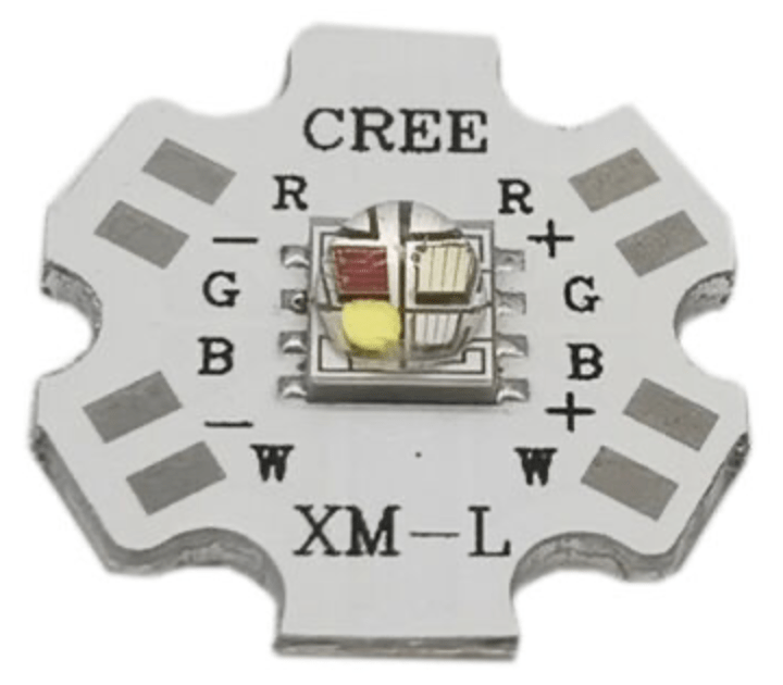
Back in September 2021 I conceived the idea of designing a very compact, waterproof RGBW spot/flood light that can be daisy-chained and independently controlled, similar to an addressable strip or string. The 12W Cree XML RGBW module is still the star of the show; I haven’t found anything better yet.
A 4-channel (RGBW) constant-current driver will be integrated into the light enclosure, but the digital PWM controller will be implemented in a separate board/enclosure. The PWM controller will have many more features that a typical addressable pixel, and will be be MCU-based, so it’s not possible to squeeze this into the light fixture enclosure. But a single controller will be able to control four FidoLights. I’ll describe this controller (called the Flex controller) in a separate post.
My original constant-current (CC) driver circuit was designed to provide up to 700mA of per-color current. The goal of my latest design (more below) is at least 1.0A, with an upgrade path to 1.5A. The current version of the Cree XML LED has a maximum rating of 1A, but there’s a new version on the horizon that can handle 1.5A with a corresponding increase in brightness.
Constant-Current Driver
If you’ve read my previous posts on this subject, you know that I’ve gone through multiple iterations of the CC driver circuit and have tried several different buck converter chips. One challenge has been an ever-changing set of component supply issues, forcing me to change the design when components become unavailable. Another challenge has been achieving a reasonable level of circuit efficiency, which in this context refers to the amount of power lost (dissipated) in the process of down-converting from the 12v input voltage to the current-regulated LED output at the LED’s forward operating voltage (VR). The Cree XML RGBW LED’s per-channel forward voltages (typical) are as follows: Red – 2.25v, Green – 3.3v, Blue/White – 3.1v.
Buck (step-down) converter chips (as opposed to boost converters) are used as the basis for constant-current LED drivers when the input voltage is higher than the LED’s forward operating voltage (VR). Conversion efficiency can range from 75% to 95%, where efficiency increases when the difference between the input and output voltages is minimized. So that suggests two strategies to maximize efficiency (i.e. reduce wasted power dissipation):
- Use a supply voltage that’s only a little higher than the maximum LED VR.
- For each color channel, wire multiple LEDs in series so that the driver “sees” the sum of the individual LED voltages.
Unfortunately I couldn’t use either of these strategies. Each light fixture only contains a single Cree XML module, with a single LED per color channel. And I really wanted to use a 12v power source, since I’ve standardized on 12v (and occasionally 24v) for all of my projects. So for my latest design I’m only expecting to achieve 82% efficiency. For example, if both the Red and Green channels are being driven at 1A, the power consumption of the LED module itself is (2.25v x 1A) + (3.3v x 1A) = 5.6W. Of this power, only a small fraction (perhaps 20% or less) is converted to light energy, with the rest being dissipated as heat. So let’s say that the power (heat) dissipation in the LED module is 5.6W x 0.8 = 4.5W. It’s possible that the LED power could be somewhat higher, but I think in general it’s safe to says that no more than two color channels will be simultaneously on at maximum brightness for any extended period of time.
Given that the LED module needs a maximum of 5.6W and that the driver circuit has 82% efficiency, the total power required from the power supply is 5.6W / 0.82 = 6.8W. The power consumed by the CC driver circuit will be 6.8W – 5.6W = 1.2W, and all of this will be dissipated as heat from the buck converter chip and its associated components. So the total heat dissipation inside the light enclosure is 4.5W + 1.2W = 5.7 Watts. That’s quite a bit of heat energy! See further below for my plans on how to deal with that.
Buck Converter Chip
My original plan (12+ months ago) was to use the Diodes Inc. AL8861 buck converter chip, partly because it’s closely related to the now-obsolete AL8860 chip used in the SparkFun PicoBuck board. But because the AL8861 wasn’t available at the time, I designed my first PC board using the Richtek RT8471 chip. I was never able to get that board working correctly, so I then switched to the Texas Instruments LM3405A. That version worked, after some component tweaking, but I wasn’t really satisfied with the result. One problem was that the LM3405A requires more external components than other buck converter chips, making the board bigger than I had hoped. To save space, I used non-drilled copper pads for the connections to the LED module and to the external controller. That made it difficult to assemble the board into the complete light fixture.
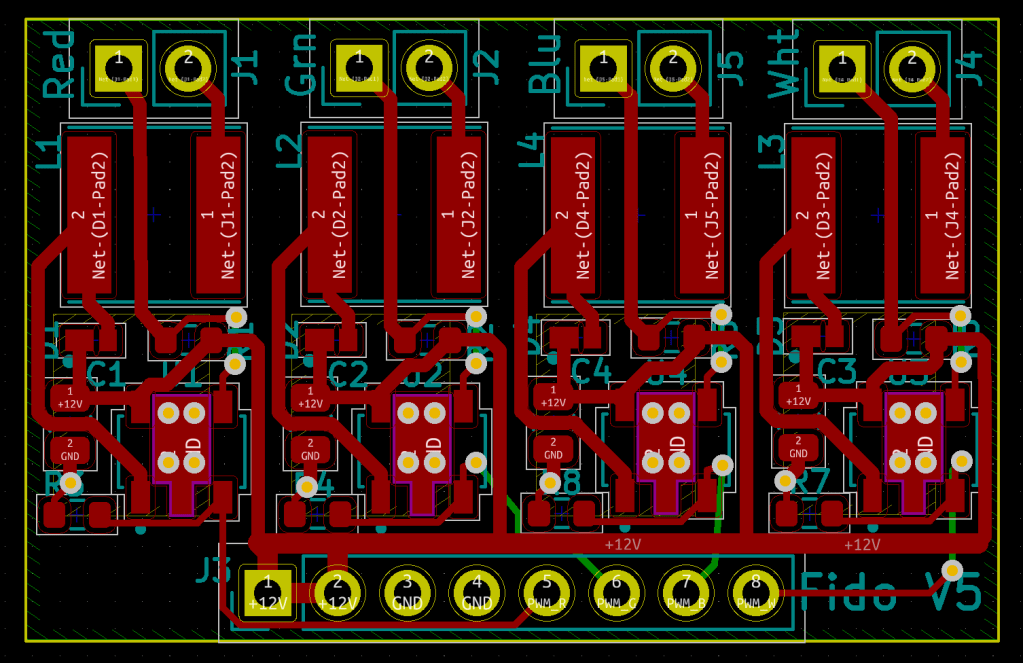
Now that the AL8861 is again available (and cheaper than many other chips), I’ve designed the 5th revision of the FidoLight driver board. It’s only 1.4″ x 0.9″ (35.5mm x 22.5mm), about the same as the previous version, while providing drilled pads for making the external wire connections.
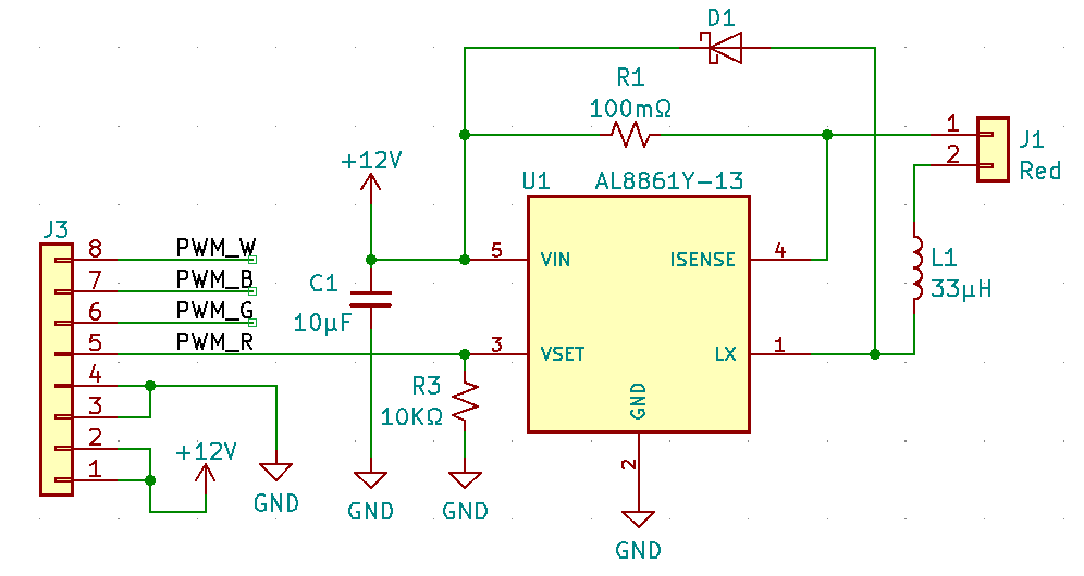
One channel of the circuit is shown at right. For each channel, the board accepts a logic-level PWM signal that linearly controls the LED current between 0 and 1A. The AL8861 uses a sense resistor (R1) in series with the LED to measure the instantaneous current. Using this measurement, it implements a switched-mode current control loop operating at about 290KHz. It’s interesting to note that the PWM input of the AL8861 is actually an enable/disable pin. When the PWM signal is high, the current control loop is enabled so that the maximum current (ILED(max) = 1A) flows through the LED. When the PWM signal goes low, the LED current is completely shut off. This means that the average LED current ILED(avg) = ILED(max) x (PWM duty cycle). This works because the recommended PWM frequency (500Hz) is much lower than the current loop frequency (290KHz), giving the loop time to stabilize during the “on” phase of each PWM cycle (for duty cycles above about 0.2%). And because the PWM frequency is much faster than the response time of the human eye, there is no detectable flickering and the LED is perceived to have a constant brightness level that is based on the average current ILED (avg).
Cooling
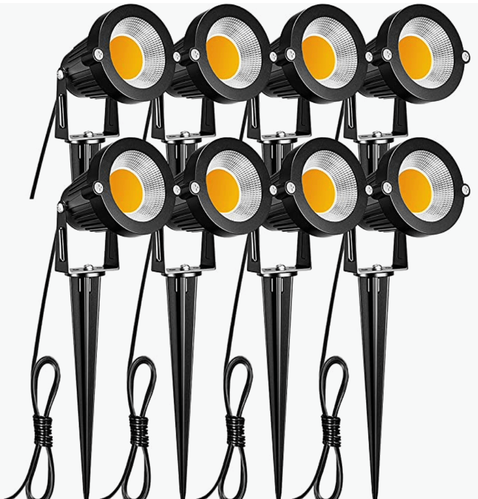
Early in this project I decided that rather than trying to design and build my own weatherproof enclosure, I’d “repurpose” the enclosure from some inexpensive landscape lights. I selected these lights, which cost $50 USD for 8 lights, and I haven’t found any better options so far. I just remove the white COB LED and associated electronics/cable, keeping only the enclosure, the swivel base, the reflector, and the metal LED mounting plate. I may use the ground stakes (which are quite sturdy) for some projects.
As described earlier, a maximum of 5.7W of power will be dissipated as heat within the enclosure, when the light is operating at maximum (2-channel) brightness. Since there will effectively be no airflow within the enclosure, the goal is to ensure that there is a low-resistance thermal conduction path from each heat source to the outside of the enclosure, where the heat can be dissipated into the ambient air by both thermal radiation and thermal convection.
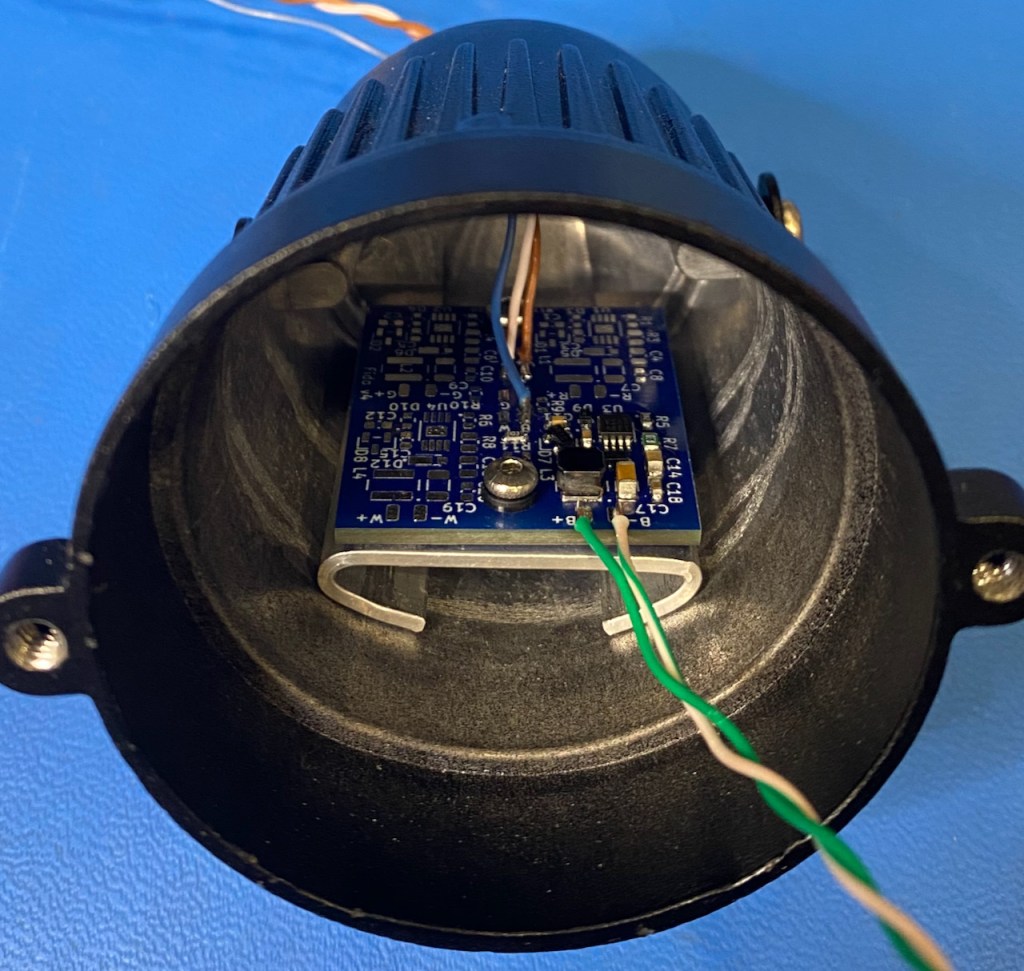
The first step is to provide a thermal conduction path from the driver board components (at least the hottest ones) to the enclosure. This is accomplished with a custom aluminum heatsink attached to the back of the board. The photo at right shows the previous version, where the board was attached to the heatsink with two screws. To save space on this version, I decided to omit the screws and use an adhesive thermal pad. To attach the heatsink to the enclosure, I’ll probably use some type of thermally-conductive adhesive.
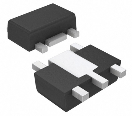
The AL8861 chip is available in three package types, and I chose the SOT89-5 package, which incorporates a large heatsink pad on the bottom. The driver printed circuit board (PCB) is designed to promote heat transfer from the AL8861 and other components to the heatsink on the bottom of the board.
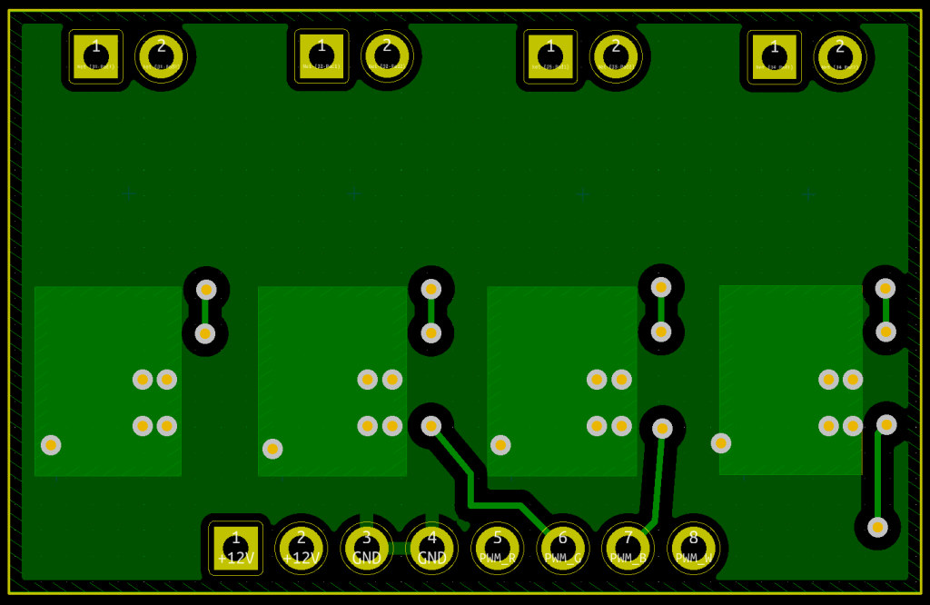
The PCB is only two layers, and the majority of the back side is a 1oz copper fill connected to the circuit ground (i.e., a “ground plane”). Four via holes directly underneath each of the AL8861 chips promote heat transfer to the backside ground plane. Furthermore, four large openings are created in the backside solder mask to increase thermal conductivity in the hottest areas of the board. The copper in these areas will be solder-coated via a typical hot-air solder leveling (HASL) process. These areas will be insulated from the aluminum heatsink by the non-conductive thermal pad.
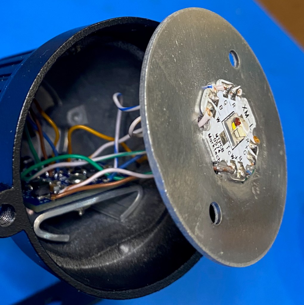
The other major heat source is the Cree LED, which comes pre-mounted on an aluminum “star” module. This module will be attached to the salvaged LED mounting disc with non-adhesive thermal paste, since it will end up being clamped in place by the reflector and front cover ring assembly. Note that I had to drill additional holes in the disc to accommodate the 8 wires needed for the RGBW module.
The disc rests on a circular “shelf” inside the enclosure, and here again I’ll use non-adhesive thermal paste and rely on clamping pressure from the cover assembly. The use of non-adhesive paste makes it easier to access and replace internal components, but the significant downside that it’s very messy, and manages to get on everything!
As you can see, I’ve put some effort into providing thermal conduction paths for everything that gets hot. But will it be enough? I have no idea! I decided not to attempt a heat flow analysis, and will rely on lab test results.
Next Steps
I’ve been out of town while writing this post, and since I left the FidoLight v5 PCB and all of the components have arrived on my doorstep. I’m very eager to get one assembled to see how it performs, and I’ll be sure to drop another update post in the near future.
I’ve also received the PCB and components for the 1st version of the Flex controller (controls up to 4 FidoLights), so I’ll be posting about that, too.
Thanks for reading!

Interesting to follow you progress Keith. All the best with the heat flow!
LikeLike