

In a recent post I described my progress in developing a very compact RGBW floodlight that I plan to use for both art lighting and landscape lighting projects. I have an existing controller (the SLiC v2 board, described in this post) that is able to drive two of these “Fido” floodlights. But I challenged myself to come up with a new board that could drive four floodlights and would also be significantly smaller than the SLiC board. This led to some interesting design choices and tradeoffs.
Since the controller is intended for outdoor applications, I started by selecting an appropriate weatherproof enclosure. I’ve been really happy with the Rose Enclosures brand of IP66 ABS boxes that I used for the Manta Ray and Desert Shark projects to house both the SLiC v2 and SLiC v3 boards. Fortuitously, Rose makes another box with the same length and height, but is one-third narrower. So that set my goal for the PC board dimensions.
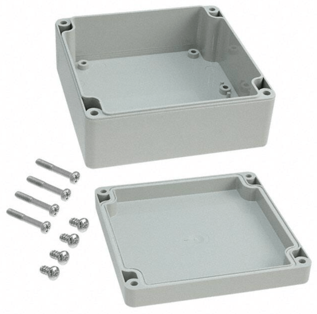

I couldn’t really go any smaller than that because the enclosure needs to accommodate four PG7 cable glands on the long side.
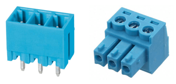
In all of my controller development projects so far, I’ve found that connector choices have a huge impact on PC board size and layout. In my article Weatherproofing Techniques for LED Lighting Systems, I described my preference for 3.81mm pitch pluggable terminal block connectors (header, plug). When used with wire ferrules, these work great when the external cables use stranded wire in gauges between 20 and 14 AWG, and when the maximum current per conductor is greater than 2 amps. For example, a full-length WS2815 LED strip (5m, 300 LEDs, 12v) requires a maximum current of about 4A. This current is carried by two of the three conductors in the 3-conductor cable, so a 3-pin pluggable terminal block (rated for 7A) is a perfect solution.
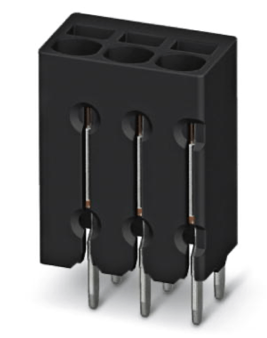
But driving the Fido lights presents a different set of requirements. The interface between the Flex controller and each of the four Fido lights consists of six signals: +12v, Ground, and four digital PWM signals (RGBW). The maximum supply current is only 0.9A, and obviously the digital signals are very low current. Given the larger number of signals, and the lower current requirement, I decided to use a more compact connector that still has the advantages of the pluggable screw terminals. I selected a 2.5mm pitch, 6-pin push-in terminal block. With this type of connector, a bare wire (or a wire ferrule) is pushed into the round openings, where it is captured by a leaf string contact. The wire can be removed by inserting the tip of a (very) small screwdriver into the adjacent square opening, releasing the spring force. The contacts can accept wires between 24 and 20 AWG, and are rated at 6A.
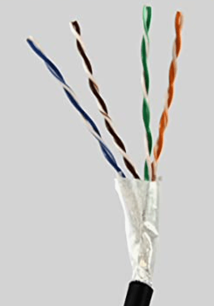
For the four Flex-to-Fido cables, I selected outdoor-rated Cat5e ethernet cable. This type of 8-conductor cable is widely available and very inexpensive ($0.30/foot). It consists of four pairs of 24 AWG solid wire. The twisted-pair characteristic isn’t important in this application, so I’ll just be using six of the conductors. An added bonus with this type of cable is that both the jacket and individual wire insulation are very easy to strip, and the 24 AWG solid wire works well with the push-in terminal blocks.

Internally, the Flex controller is very similar to my previous boards. As always, it’s based on a PJRC Teensy 4.0 microcontroller unit (MCU). Until now, my controllers have only needed 8 digital outputs to drive addressable or non-addressable (“analog”) LED strips, the latter with MOSFETs to provide the necessary drive current. Since the Flex board needs 16 outputs, I had to do some shuffling to free up some pins. In doing so, I was left without enough input pins to read the 5-bit DIP switch that indicates the board’s SlicBus node address in a multi-controller system. As shown in the full schematic below, I ended up sharing 5 of the LED output pins.
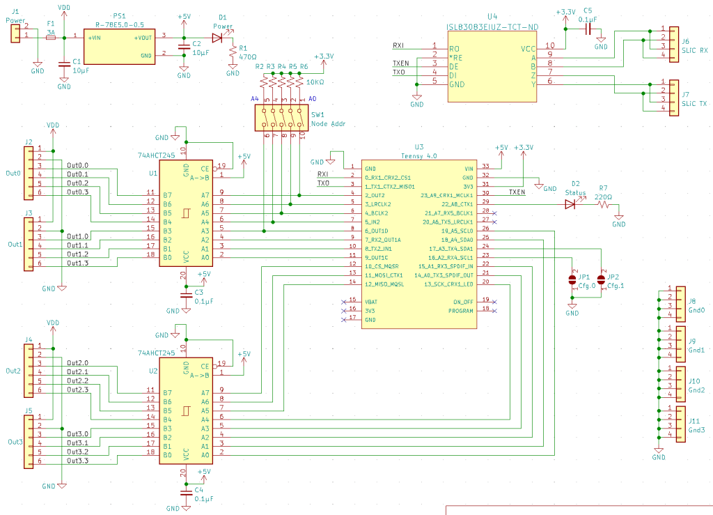
As with the previous controllers, I use 74AHCT245 chips to level-shift the 3.3v logic outputs from the MCU. This provides robust compatibility with addressable LED strips that operate using 5v logic levels, and improves the capability of the board to drive longer cables and reject interference. On power-up, the shared GPIO pins will be configured as inputs while the DIP switch setting is read, and then reconfigured as outputs for normal operation. The large (10KΩ) pull-up resistors will not interfere with the MCU output signals.
The Teensy 4.0 MCU provides 20 PWM-capable output pins, of which I’m using 16. All of these can be configured for a wide range of PWM frequency and resolution. To achieve smooth color and brightness fades when the board is configured to drive Fido lights, I chose 12-bit PWM resolution and 500 Hz PWM frequency. This frequency is the maximum recommended for the AL8861 buck driver chip used in the Fido design.
Like the SLiC v2 and SLiC v3 boards, the Flex board is intended to operate as a “remote” node in a distributed, multi-controller system. The remote nodes receive commands from a single “master” controller via a multi-drop RS-422 serial bus that I call the SlicBus. The SlicBus uses a single differential signal pair at 3.3v logic levels, and is configured to run at 250 Kbps. For the Manta Ray and Desert Shark projects, my FLiCr board is used as the master controller. I’ll continue to use the FLiCr board for the time being, but it’s due for an upgrade.
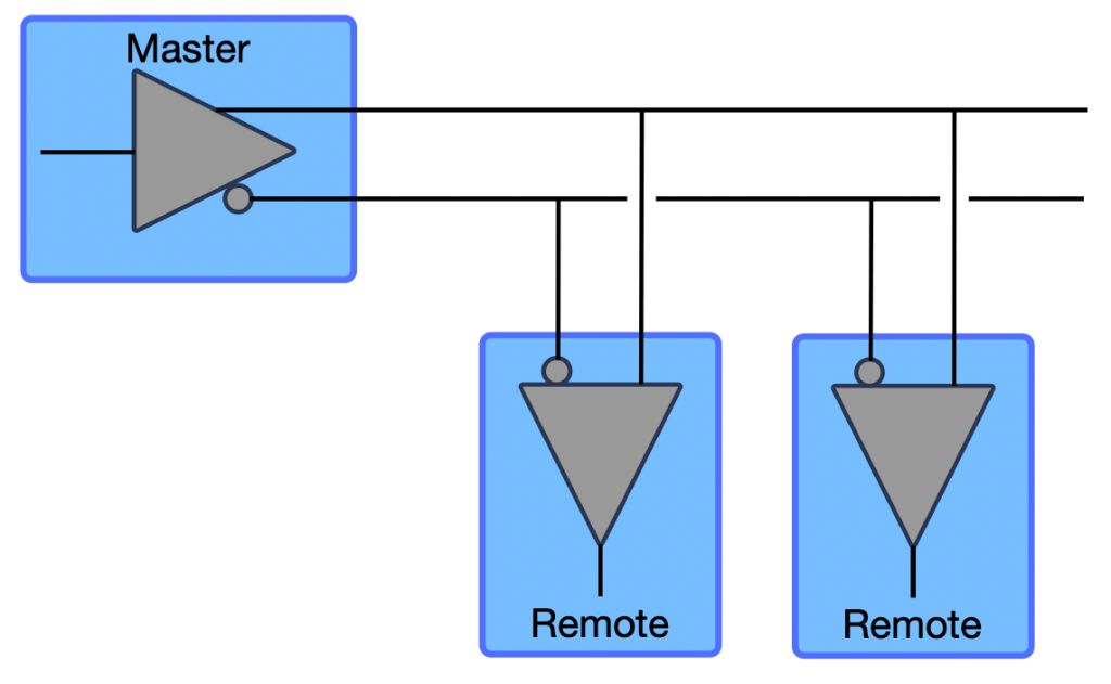
On the previous remote controller boards I used the MAX3281 single-channel RS-422 receiver, creating the single-transmitter, multi-receiver architecture shown at right. Each remote board receives all of the command frames transmitted by the master controller, and uses its unique 5-bit node address to determine which command frames it should process and which it should “drop”.
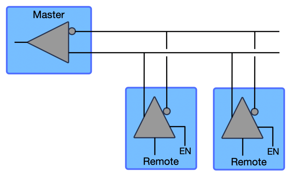
This communication approach has worked fine, but there are some occasions when it would be helpful for the master to receive some information back from the remotes. At minimum this could help with debugging, since the remote controllers are often in difficult-to-access locations in a large artwork. For the Flex controller I’ve switched to the ISL83083E RS-485 transceiver chip. This chip has a single receiver that allows me to use exactly the same master-to-remote communication paths as shown in the diagram above. It also contains an independent transmitter that I’ve used to implement a separate remote-to-master communication path, shown at right. Since this is a multi-transmitter, single-receiver architecture, only one remote controller at a time can enable its transmitter. This is done with some minor extensions to the SlicBus command protocol, where the master controller specifically requests data from a single remote node. This tells the remote controller to enable its transmitter, and to send the data within a time period indicated in the command from the master. Stay tuned for a future article on the details of the SlicBus and its communication protocol.
Although the SlicBus was originally intended to carry both data and power for the remote nodes, I never ended up using it to carry power. So now the SlicBus just requires one differential twisted pair for the master-to-remote path and another pair for the remote-to-master path. I use the same Cat5e cable as for the Flex-to-Fido connections, this time depending on the twisted pairs for protection against interference on the long cable runs. On the board I used two 4-pin push-in terminal blocks for the separate receiver and transmitter connections. Four pins on the terminal blocks enables making the “upstream” and “downstream” cable connections without any wire splices (see schematic).
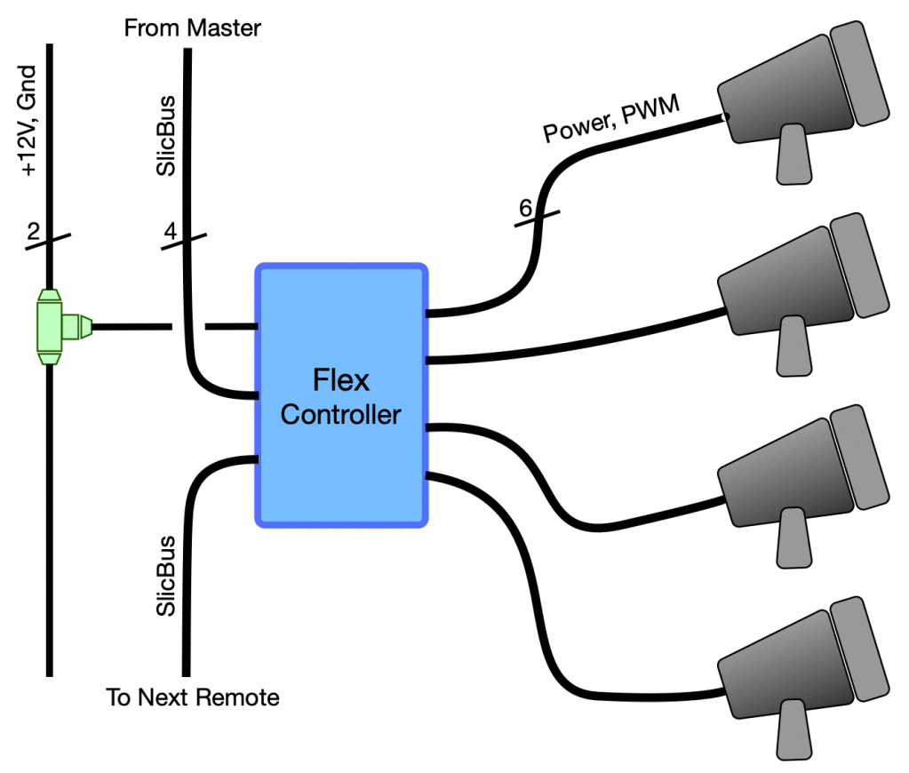
The diagram at right shows the Flex controller connections in the “max Fido” configuration. Note that the 2-conductor power cable (likely to be 18 AWG in most applications), is tapped to provide a stub connection to each of the Flex boards. I chose this approach to avoid routing the power lines though the Flex PC board. In previous projects, I’ve used this IP68 3-way junction device. It’s a bit expensive, but has worked week for me.
OK, hopefully I haven’t put you to sleep with all that. There’s actually one more topic that I wanted to talk about, but I think I’ll save that for a future post. It’s a new idea that I’ve been developing for power and signal distribution in a large lighting system involving multiple power supplies and lots of power-hungry addressable LED strips. And of course, the new Flex controller fits perfectly into that architecture…
Thanks for reading! As always, comments, suggestions, and questions are always welcome, either here or on Reddit (u/Aerokeith).

Hello Keith. This board looks like it’s going to serve you quite well. Appreciate your insight.
One typo I spotted: 47AHCT245, but should start with 74.
Cheers,
-marc
LikeLike
Oops! Thanks for catching that!
LikeLike
Nice job Keith. You usually don’t describe the microcode, is that your secret sauce or if there a way for us less code proficient to learn.
On that 3 way two wire connector, you might consider a visit to AliExpress. About 1/4 of the Amazon cost and probably from the same factory. https://www.aliexpress.us/item/2251832780426863.html?spm=a2g0o.productlist.main.73.46ab864asNbw2c&algo_pvid=95952941-f0b9-4c0d-acac-6c0cc541f7bf&algo_exp_id=95952941-f0b9-4c0d-acac-6c0cc541f7bf-36&pdp_ext_f=%7B%22sku_id%22%3A%2266595074698%22%7D&pdp_npi=2%40dis%21USD%213.79%212.2%21%21%21%21%21%40210217c716690538096423301d0748%2166595074698%21sea&curPageLogUid=pqGvihQAsZP4
LikeLike
Thanks for the heads up on the connector. I’ll give it a try, but I’ve found that there’s a huge difference in the quality of T-connectors from different manufacturers.
You’re correct that I write less frequently about software topics, but it’s not because I’m trying to keep secrets. Some of my code is in a public GitHub repository, and if you shoot me an email (keith@electricfiredesign.com) I’ll give you the links.
Probably the “best” software article I’ve written so far is the one on multi-tasking (https://electricfiredesign.com/2021/03/18/simple-multi-tasking-for-arduino/). The techniques described in this article are at the heart of all my code.
I find writing about software to be more challenging that writing about hardware and other topics. And I struggle to find software topics that I think would be of general interest, since many aspects of my software approach are a bit unique and specific to my requirements. But I’m open to suggestions for topics. One article I’m starting to think about will cover reliable serial communication in a multi-controller system, basically what I’ve implemented for the SlicBus described in the “Flex Controller” article.
LikeLike