
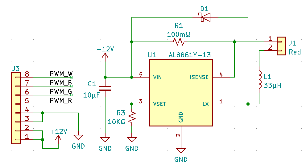
One of my recent posts described the design details of the latest iteration of my 4-channel buck constant-current driver board that’s intended to be used with a high-power Cree XML RGBW module. As mentioned at the end of the post, I just received the bare PCB v5 boards from PCBWay, and the components from Digi-Key, and I was very anxious to assemble a board and find out if it performed as expected. I had been disappointed to various degrees by previous iterations, so my fingers were definitely crossed (but not while soldering).

A quick digression about my approach to PCB assembly. Since my boards are used in very low quantities, only for my own projects, I haven’t yet taken advantage of PCBWay’s board assembly services. My first couple of boards used all through-hole components, but I quickly graduated to surface mount (SMT) components. I initially hand-soldered all the components, which was challenging but doable if I restricted my self to larger passive components (0805 and bigger) and avoided very fine-pitch ICs. Then I heard about hot air soldering stations. Although these are most commonly used for board rework, they also work great for initial assembly. The most inexpensive units sell for less than $40 USD, but I splurged for a high-quality unit, the Quick 861DW, shown above, about $300 USD. I’ve had great success with this station using 0603 passives and 0.5mm pitch ICs. If I ever need to crank out higher volumes, I may think about purchasing a small reflow oven, or try using an assembly service.
Anyway, the board went together nicely, without any component footprint issues (not an uncommon problem for a new design). Although the AL8861 requires a much larger inductor (33µH) versus the one in the previous v4 design based on the LM3405A (6.8µH), the v5 board is smaller significantly smaller than the v4 board. Eliminating the heatsink mounting screws helped.

OK, so how did the Fido v5 board perform? Well, all of my initial test results conform pretty closely to the analysis that I had done based on the AL8861 data sheet. Yippeee!

The first big test was to confirm that the driver accurately regulates the LED current. With a sense resistor value of 0.1Ω and with the enable input (VSET) driven high (i.e. no PWM), the expected LED current is 1.0A. I measured the current with a Micsig CP2100A current probe, which has an accuracy of about 8%. I captured the results with photos of the screen of my relatively low-end oscilloscope, a Siglent Technologies SDS1202X-E. The screenshot below shows an RMS voltage of 1.01V, which translates to a current probe reading of 1.01A. Pretty much spot on!

The roughly triangle-shaped “ripple” in the waveform is an expected characteristic of any buck converter circuit. The AL8861 data sheet indicates that the ripple should be 26% peak-to-peak. This looks closer to 35%, but I’m not going to worry about it.
The next test was to see the driver’s response to PWM pulses. As described in the previous Fido update, the buck converter circuit (which regulates the LED current at 1A as shown above) is only enabled during the “high” portion of the per-channel PWM signal for each 500 Hz cycle. This behavior is shown in the screenshot below. The PWM pulse (yellow trace) is 19.6µS long, which represents a 1% duty cycle for a 500Hz PWM frequency.

After a brief start-up delay from the time the PWM signal goes high, the LED current starts to rise. The closed-loop current control circuit then kicks in, maintaining the RMS current at 1A for only a few cycles until the PWM signal goes low. This repeats every PWM cycle, and when measured over that period, the average LED current is 1% of 1A, or 0.01A. The human eye doesn’t see any of that, and just perceives that the LED is very dim.
I won’t show the results here but I also confirmed that the circuit responds appropriately to the full range of PWM duty, up to 100% and down to about 0.2%, as expected.
The next test was to determine the efficiency of the driver circuit, which is the ratio of power delivered to the LED and the total power consumed by the LED plus the driver circuit. So the higher the power consumption/dissipation in the driver circuit, the lower the total efficiency.
When the 290KHz current control loop is “on”, current flows from the 12v power supply, through the sense resistor, the LED, the inductor, and finally through the MOSFET switch inside the AL8861 chip. This occurs during the upward-sloping portion of the purple curves in the screenshots. The sense resistor, the inductor, and the MOSFET all have DC resistance that results in power dissipation when current flows through them. When the control loop turns “off” (i.e. when the MOSFET turns off), the inductance of the inductor causes current to continue flowing (although decaying in a downward slope) through the inductor and the Schottky diode. In addition to the resistive power loss in the inductor, power is also dissipated due to the fixed voltage drop of the diode (about 0.5v).
I analyzed the driver efficiency on a per-channel basis when operating at 100% duty cycle. I measured three parameters: the LED current (should be 1.0A RMS), the total current delivered by my bench power supply (set at 12.0v), and the forward voltage drop (Vf) of the LED. Here are the results:
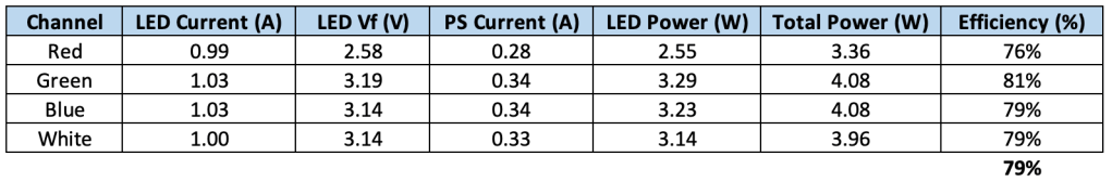
So the driver circuit efficiency, averaged across all four channels, is 79%. That’s within the measurement margin of error compared to the 82% efficiency that I expected based on my interpretation of the graphs in the AL8861 data sheet. I’ll call that a win!
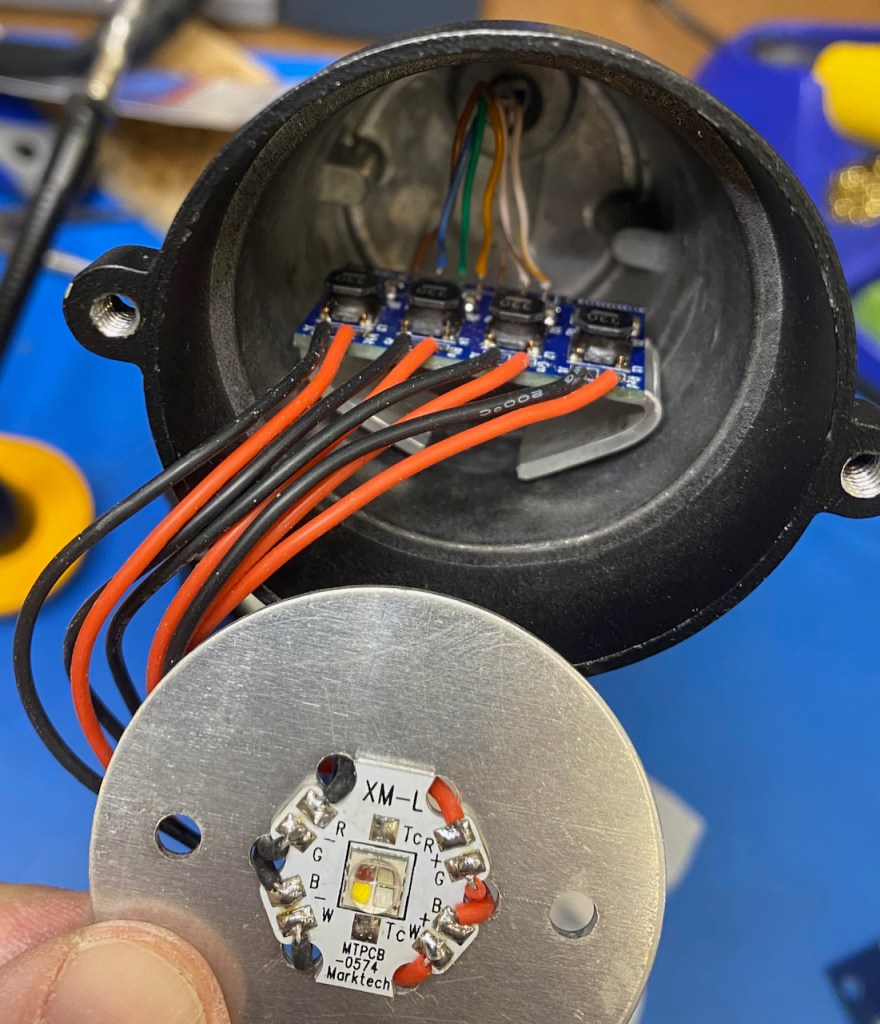
Below is a photo of my test setup, using my new Flex board to control the Fido:

I’ve gotten better at soldering wires to the contact pads on the LED module, especially now that I switched to very flexible 26 AWG wire with silicone insulation that doesn’t shrink back during soldering. The aluminum LED module is attached to the mounting plate (part of the hacked light housing) with thermally conductive adhesive. The mounting plate rests on a ledge inside the housing, and I’ll use non-adhesive thermal paste to provide a good thermal connection to the housing. I used non-adhesive paste here so that it would be easy to remove and replace the LED or Fido board. The LED mounting plate is held in place by the reflector and lens assembly that screws to the front of the housing.
In preparation for some thermal testing, I’ve attached the Fido board to my very crudely hand-bent heatsink with an adhesive thermal pad. The heatsink will be affixed to the housing with the same thermal adhesive used for the LED module.
Note that I’ve swapped out the temporary ribbon-cable connection to the Flex board with Cat5e cable, using 6 of the 8 conductors. For the initial testing I’m using a 6 foot (1.8m) length of cable, and I’ve confirmed that good signal quality is maintained for the 4 PWM signals.
After I’ve finished assembling the prototype Fido light fixture, I’ll measure the steady-state temperatures on the LED module and driver board when being driven under worst-case conditions. The results of these test will help me estimate the expected reliability/lifetime of the lights.
OK, that’s it for now. I’m writing this on 24 November (Thanksgiving Day in the US), and later today we’re hosting a Friendsgiving party for some neighbors and friends. My very supportive and tolerant wife is putting the finishing touches on the meal, and I’d better go lend a hand.
Thanks for reading!
Looking for more articles about LED lighting? See the Electric Fire Design Blog Index for a complete list of articles!

2 thoughts on “FidoLight RGBW Spotlight: Update #7”