I’ve been distracted on other projects, but now I’ve managed to follow through on everything I proposed in Update #4. The v4 revision of the FidoLight board is now just a 4-channel constant-current driver, and all the control functions are now moved to a very flexible Distributed Lighting Controller (DLC) board that can drive two light fixtures of various types (including the FidoLight).

The Fido v4 board can theoretically drive up to 1A per channel, but for now I have it configured for about 0.7A. Since the board will be mounted inside the waterproof light fixture enclosure along with the RGBW LED module, I’m expecting that there may be some thermal issues to contend with.
The v4 board uses the same LM3405A buck driver chip as v3, but with a slightly different configuration of the external components (one of the options shown in the data sheet). I messed up the footprint for a zener diode, which for some reason is in a SOT-23-3 package. Rotating the part allowed me to make the correct connections without hacking the board, so it’s fine for now. The board performed well in my initial tests, achieving about 80% efficiency, which is about the maximum that can be achieved with this part when driving only a single LED per channel.

As shown the in the photo above, the Fido board is screw-mounted to an aluminum plate with “wings” that touch the inside of the enclosure. There’s a 0.5mm thermal pad between the board and plate, but I’ll also experiment with thermal paste to see which works better. The backside of the board is mostly covered with solder mask, with small “bare metal” (tinned copper) sections under the four driver chips to improve thermal conductivity. I plan to use thermal epoxy to attach the board/plate assembly to the enclosure.

The first rev of the DLC board seems to be working well. Depending on the amount of power required by the attached fixtures, more than 20 of these boards can be connected on a daisy-chained power/data bus using weatherproof 8-conductor, 24 AWG Cat5 cable. The two 8-pin push-in terminal blocks in the middle of the board are for connecting the upstream and downstream bus cables. Six conductors are used for power/ground (12v or 24v) and the remaining two for a differential RS-422 data bus (unidirectional) that is driven by a single master controller.
The DIP switch is used to generate a unique 5-bit address for each node on the serial bus. The master controller will be able to drive multiple busses, so a complete system is not limited to 32 nodes.
The two 6-pin terminal blocks at the bottom are for connections to a FidoLight or other type of light fixture. The discrete components below each connectors can be loaded in different configurations to support any of the following:
- Four digital PWM signals (RGBW) to a FidoLight or similar “intelligent” fixture. The Teensy 4.0 MCU is configured to drive these PWM outputs at 1KHz with 12 bit resolution.
- Three or four open-drain PWM outputs that can sink up to 1A each, to be used for driving high-power RGB or RGBW fixtures like this one.
- Up to four high-speed digital outputs that can each control an addressable LED strip or fixture that accepts the WS2811/WS2812b serial data protocol.
A 74AHCT245 driver is used to translate the 3.3v data signals from the Teensy 4.0 to the 5v logic levels required by the FidoLight and by most LED strips.
A replaceable, low-profile automotive-type fuse provides protection against short circuits. To the right of the fuse is a push-in terminal block that provides alternate power/ground connections. This terminal block accepts heavier-gauge wire (up to 14 AWG), and can be used when the Cat5 bus cable is inadequate to provide the higher currents that may be required by some fixtures.
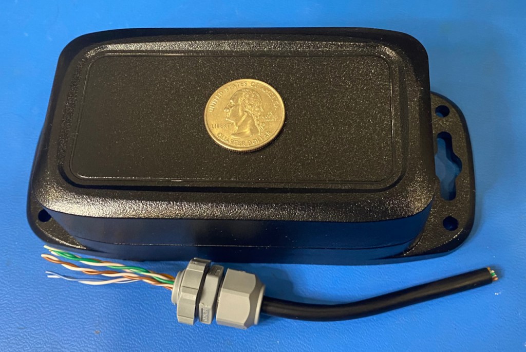
The DLC board will be mounted in the IP68 enclosure shown above, with waterproof cable glands for all external connections.
Next steps:
- Build a complete FidoLight assembly and perform additional thermal testing.
- Install a DLC board in the enclosure with a full set of cables/glands to ensure there are no mechanical issues.
- Complete the DLC firmware, about 70% of which can be ported from previous projects.
- Start thinking about the design of the master controller. In addition to driving the DLC boards, this controller will also interface with various sensors: ambient light, motion, etc.

6 thoughts on “FidoLight RGBW Spotlight: Update #5”