
Lots of progress to report. I’ve assembled the first prototype and have run a series of tests to validate the design. So far everything has worked almost perfectly and my list of next-revision improvements is very short. One of the most important tests was to confirm the functionality and performance of my “reconfigurable LED driver circuit”, as described in my original FLiCr blog post.
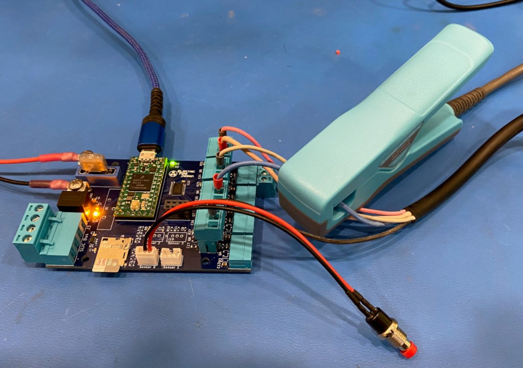
The prototype was configured to drive four addressable LEDs strips using the four pluggable terminal blocks on the far right edge of the board. The other four terminal blocks (adjacent to the others) were configured to drive a high-power RGBW flood light. Unsurprisingly, the addressable LED strip outputs worked fine driving a 12V WS2815 LED strip, since the circuit is very similar to ones that I had successfully used pin the past. Just a level shifter (a 74AHCT245 in this case), a 33Ω series resistor, and a 10µF filter capacitor.

I was a bit more nervous about testing the PWM output configuration, which uses the 74AHCT245 as a gate driver to improve the switching performance of the DMG3402L MOSFETs. I tested the circuit using the 24V, 48W RGBW flood light shown at right. Based on previous testing of this light, each driver channel must sink up 0.4A continuously to achieve full brightness. With a relatively low RDS(on) of 65mΩ, the static MOSFET power dissipation would be P= I2R = (0.4)2 x 0.065 = 0.01W. Phhht! Practically nothing! However, if the MOSFET is not driven fast enough (in terms of gate charge/discharge rates), considerable additional power will be dissipated as the MOSFET’s drain-source current path turns on and off. I’ll need to do more testing to fully characterize this aspect of performance, but my semi-calibrated finger couldn’t detect any device temperature rise when driving the fixture at a 1KHz PWM frequency and various duty cycles. I’ll call that a success!
I retested the per-channel current levels with my new Micsig CP2100A current probe. The results were a bit unexpected, as the current in each channel looked like this at 100% duty cycle:
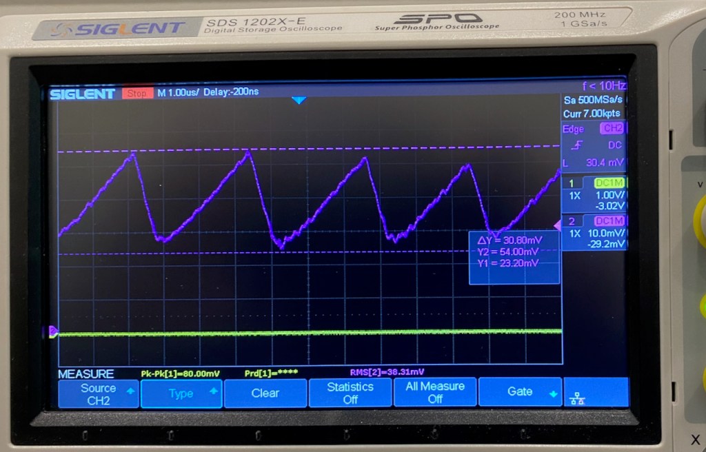

I had originally assumed the internal design of this flood light was very simple. Given its current-sink type interface, I had assumed it just used series resistors in each channel to limit the LED current levels (I had seen this in another less expensive flood light). But the ~300KHz ramp on the current waveform suggested that something else was going on. So I opened up the case to take a look.
Interesting…the board appears to be a 4-channel constant-current driver, where the driver circuit for each channel is “powered up” when its input is grounded by the MOSFET on the FLiCr board. That explains the ramp waveform. The current-control loop must operate at 300KHz. I’m a bit surprised by the peak-to-peak variation, but the RMS value of the current waveform exactly matches my previous current measurements performed with a DMM.
Another semi-interesting point: The manufacturer advertises the flood light as “48W”. Even if you ignore the lunacy of simultaneously driving all four inputs (R+G+B+W) at 100% duty cycle, my measurements indicate a maximum power of 24 x (0.29 + 0.38 + 0.39 + 0.38) = 35W. Maybe it consumes more power at higher temperatures? Hard to believe it would be 37% more…
Another big test of the FLiCr design was to confirm the ability of the SLiC Bus to distribute power and multi-drop serial communication over long distances. For this test I used the FLiCR board with the DLC SliC (remote node controller) board. The SLiC board is described in these two blog posts (#1, #2). The SLiC board is shown in the photo below, on the left.


For this test, the two boards were connected with 10m (33′) of Cat5 cable, using six of the eight wires to provide 12V power to the remote SLiC board.
On the FLiCr board, I wrote a simple program to send a 1-byte command on the SliC Bus serial interface every 10ms, where the command byte increments from 0 to 255 and repeats. The program on the SliC board reads the command byte and uses it to update the hue of the attached LED strip. Even without any termination on the RS-422 bus, the serial data signal looked very clean on the scope, and the test appeared to operate flawlessly.
The next test will be to move the high-power flood light to the SLiC board, and to measure the voltage drop across the 10m of cable. My analysis shows that the worst-case voltage drop will be about 1.5V with a 10A load at the end of a 10m cable, so this relatively small load should have no problem at all. But as the saying goes: “Trust, but verify”.
Special message from the publisher/editor/writer/me:
I see you out there! The WordPress stats tell me that about 150 people a week are reading at least one of my blog posts. But very, very few people leave comments. So I want to encourage you to leave feedback or ask questions, either on the blog page or by emailing me at keith@electricfiredesign.com. I try to respond within a day or two, and I definitely don’t bite!

9 thoughts on “FLiCr LED Controller – Update #1”