If you read my recent post on the OpenRocket LED controller, you may recall that several key components are not currently available due to the supply chain issues affecting the global electronics sector. Now that I’ve used up my existing stock, I’m forced to redesign it with different parts. But I couldn’t resist making some larger changes to make it even more flexible. And that created a “rebranding” opportunity, so I’m calling this board the Flexible Lighting Controller, or FLiCr.
My posts on the FidoLight RGBW spotlight describe a Distributed Lighting Controller (DLC) board that can control two FidoLights (or multiple LED strips) in response to commands received via an RS-422 serial bus. These DLC boards will be used in larger projects where some of the light fixtures are far away (> 5m) from the power source and a centralized main controller. The DLC project is still in progress, but I realized that I needed to get started on the main controller. (Light bulb goes on over head). Aha! What I need is a single board that can be configured to operate in a standalone mode (like OpenRocket) or in a distributed-controller mode, talking to multiple DLC boards via the serial bus.
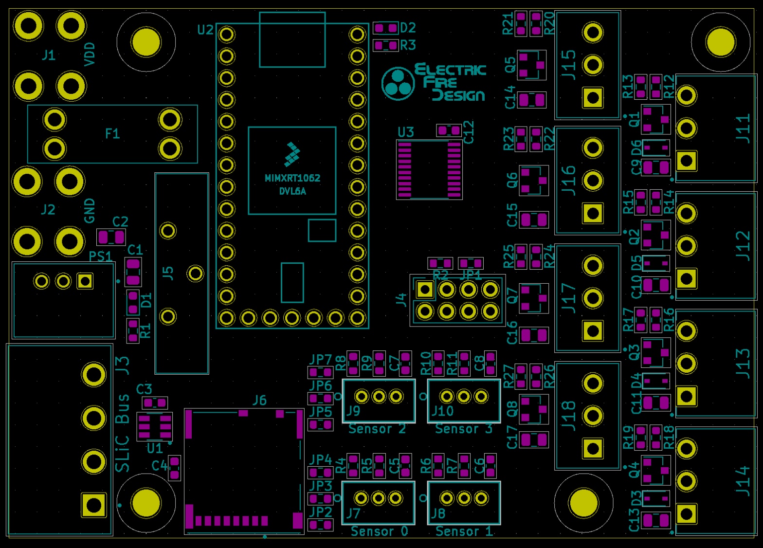
That line of thinking has been applied to many facets of the new FLiCr board design. The board can be adapted to many different applications through a combination of component-loading options, on-board jumpers, and software build options. This flexibility and additional capability results in a board that’s only 15% larger than OpenRocket.
The rest of this post will summarize the hardware design changes (compared to OpenRocket), including the underlying rationale. Feel free to comment if you think I’ve gone off the rails on anything!
Power Supply
Although I’ve standardized on 12v as the external power supply voltage for both OpenRocket and FLiCr, there are a few situations where it makes sense to use a 24v power supply. This voltage appears to be commonly used in commercial-quality LED strips, including non-addressable RGB/RGBW strips. So the FLiCr board can run on either 12v or 24v. The diagram below shows how various voltages are generated and distributed by the FLiCr board.


I’m sticking with the same 15A screw terminals for the external power supply connection. This high current capacity is needed since the 12/24v supply is distributed through the PCB to various connectors. This is really just for convenience, avoiding the need to run external wires from the power supply to each attached LED fixture.
Recent experience has taught me the value of including a fuse in the power distribution circuit. With so many external connections, there’s always a risk of a short circuit in an attached cable/connector, an LED strip, or some other external device. Although most power supplies have over-current shutdown protection, there are many scenarios in which a short-circuit results in enough current flow to cause damage, but not enough to trip the power supply’s over-current protection. While a fire is theoretically possible, the consequence I’ve see (too many times!) is damage to something on the board, like a MOSFET driver circuit. In my experience, this most commonly occurs during the installation and testing of the controller and light fixtures, especially with an inexperienced installer.


The FLiCr board includes a socketed automotive-type fuse, where the value of the fuse is chosen based on the power requirements of each application (typically between 2 and 10 amps).

The OpenRocket design included a 12v-to-5v buck converter based on a chip that’s not available for the foreseeable future, so for the FLiCr board I’m using an integrated converter module that only requires a couple of external 10µF capacitors. The version I’m using accepts an input voltage in the range 8v – 28v and can output 500mA, enough for the worst-case (power) configuration of the board.
The 5v output drives the Teensy 4.0 microcontroller unit (MCU) daughter card (same as OpenRocket). The T4 MCU board provides a 3.3v output, with 250mA current capability, that’s used to drive some of the other components on the FLiCr board.
SLiC Bus
What? That’s just the fancy name I’ve given the RS-422 based power/data bus that will drive the distributed controller boards I’ve previously described. Another rebranding opportunity: Distributed Lighting Controller (DLC) –> Secondary Lighting Controller (SLiC).
As described the FidoLight posts, the SLiC Bus consists of just four power/data signals: VDDF, Gnd, TX+, and TX-. The differential data signals (TX+, TX-) are unidirectional, and operate at 250Kbps using 3.3v signal levels. VDDF is the fused 12v or 24v power supply. The SLiC Bus is distributed to the daisy-chained SLiC boards using weatherproof 8-conductor, 24 AWG Cat5 cable. Three conductors each are used for VDDF and Gnd, creating the equivalent of a single 19-20 AWG conductor for each. This will allow the SLiC BUs to distribute 10A over a distance of 10m with a voltage drop less than 2v.
For both the SLiC BUs and for the local LED fixture connections, I’ve decided to abandon the JST-VH connectors I used for the OpenRocket design. I really like them, but availability has become an issue. I considered a few wire-to-board connector options such as the TE/AMP MTA 156 family, but they have two major drawbacks. While the 7A current capacity is enough for the LED connections, it falls short of the 10A capacity I wanted for the SLiC Bus. More important, the MTA female receptacles are insulation-displacement connectors (IDC) that only accept a single wire gauge. I really wanted the ability to use different wire types/gauges depending on the application, typically between 22 and 18 AWG.
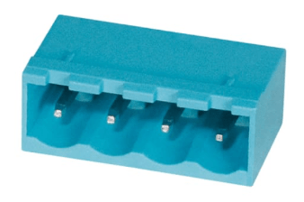
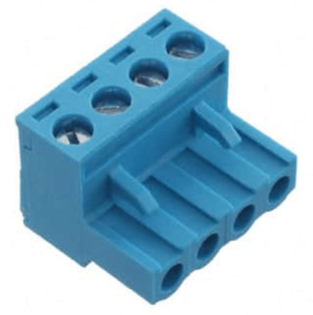
I’ve never been a big fan of screw terminals. Even though they can usually accept a wide variety of wires types/sizes, I find it very inconvenient to connect/disconnect each wire multiple times during development and testing. Not to mention the issues with frayed stranded wire and the potential need for ferrules. But I now realized that “pluggable” screw terminals might be a good solution for me, even though the cost is considerably higher than JST-VH connectors. So for the SLiC Bus connector, I chose a CUI 4-pin, right-angle shrouded header (5.08mm pitch) and a mating pluggable screw terminal. It accepts wires between 12 and 28 AWG, and the per-pin current rating is 16A. Perfect!
Switch/Sensor Inputs
The OpenRocket board supported the following types of switches and sensors:
- Two switch inputs with R-C filter debounce circuits
- One input for a passive infrared (PIR) motion sensor, requiring a 12v power supply
- One differential I2C interface intended for use with a remotely-located ambient light sensor (requiring a 3.3v power supply).
Since the I2C light sensor is no longer available, I decided to eliminate the I2C interface. For projects requiring ambient light sensing, I’ll now use a simple analog sensor like this one. In cases where there’s a significant distance from the controller to the “outside”, I’ll use fiber optic cable to couple the exterior light back to the sensor, located near the controller.

Since it’s hard to predict what types of switches/sensors I might need to interface with, I came up with the highly configurable circuit shown here. For simple switch inputs, none of the jumpers (JP2 – JP4) are needed, and the two resistors and capacitor provide a debounce filter. For a sensor needing a power source, one of the jumpers is populated (with a SMT 0603 0Ω resistor) to provide the desired voltage (12v, 5v, or 3.3v) to the connector. In this case, the series resistor is replaced with a jumper and the pull-up resistor and filter capacitor are optionally omitted. Two copies of this circuit are implanted on the FLiCr board, for a total of four inputs, with separate voltage source selection for each pair of circuits. For this circuit, I stuck with the same 3-pin JST-PH connectors used on OpenRocket.
The four sensor inputs are connected to GPIO pins on the Teensy 4 MCU that can be configured as either digital inputs or analog inputs with 10 bit resolution.
Fixture/LED Outputs
The OpenRocket board provided five addressable LED strip outputs, and four MOSFET-driven PWM outputs. The latter outputs could be used to drive several different types of device: individual high-power LEDs, non-addressable RGB/RGBW LED strips, or small DC motors, solenoids and relays. For FLiCr, I combined these capabilities into eight outputs/connectors with circuits that can be load-configured to drive any of the devices listed above. Below is a simplified version of the circuit, showing just one of the outputs.
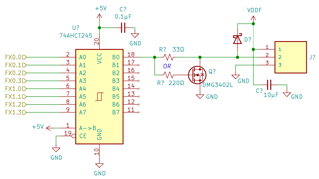
The 74AHCT245 acts as a level shifter, translating the 3.3v logic levels from the T4 MCU’s GPIO outputs to the 5v logic levels required by all addressable LED strips. It also provides higher current source/sink capability than the MCU, enabling longer cable runs from the controller to the start of the LED strip.

In the simplest circuit configuration, used to drive addressable LED strips, the 220Ω resistor, the MOSFET, and the diode are omitted, leaving just the series 33Ω resistor and the 10µF capacitor. This is very similar to the circuit used on the OpenRocket board. The 10µF capacitor (SMT 0805) across the power outputs to the LED strip is a bit on the small side, but since I haven’t found this capacitor to be necessary on smaller projects, I decided to save some cost and board space. A larger, leaded capacitor can be added externally if necessary.
In the alternate configuration, the 33Ω resistor is omitted. The 74AHCT245 then acts as a MOSFET driver, providing fast(er) charging/discharging of the MOSFET gate capacitance to minimize power consumption during switching. The DMG3402L MOSFET can sink up to 3A continuous. Combined with the 15-bit PWM capability of the MCU outputs, these outputs can drive any of the devices mentioned at the beginning of this section. The snubber/flyback diode is only needed when driving inductive loads (motors, etc.).
For the connectors I chose a smaller (3.81mm pitch) version of the CUI pluggable screw terminals described in the SLiC Bus section above. Right angle headers are used for the four connectors at the board edge, and vertical headers are used for the four “inboard” connectors. The same plugs, with an 8A per-pin current rating, are used for all eight connectors.
Remote Control

Other than the differential I2C interface, the only other major feature that I didn’t carry over from the OpenRocket design is the serial interface used to communicate with a hardwired “user interface” device. I’ve taken a leap of faith and have assumed that I’ll be able to implement a wireless remote-control interface using an inexpensive ESP8266-based WiFi module.
This module uses a bidirectional serial interface and a couple of digital control signals (board enable, reset). The FLiCr board provides a 2×4 receptacle to allow the WIFi module to be easily installed and removed as needed. The ESP8266 MCU on the module is pre-loaded with a complete WiFi protocol stack that is accessed via a rich set of AT-type serial commands. My goal (hope?) is to implement a web server in my T4 software environment, where the served web pages provide access to the same lighting configuration functions as my current “Palette” user interface device. A key point here is that the module provides a “soft access point” mode that enables a point-to-point connection with a smart phone or laptop without the need for an external WIFi network or router. Wish me luck!
Miscellaneous

Contrary to what I said in a previous post, I decided to retain the ability to install a battery to support the T4’s real-time clock (RTC). Based on a commenter’s suggestion (thanks!) I switched to a vertical CR2032 battery clip to minimize the board area consumed.
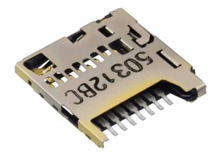
I definitely retained the microSD card, but decided that the hinged card socket I previously used was too finicky. So now I’m using a more typical push-in/push-out type socket.
What’s Next?
I’ve finished the circuit design and PC board layout and have purchased the components for a first limited-production run. I’ll submit the design to my favorite PCB fabrication house (PCBWay) within the next few days. So if you have any suggestions for improvements, please don’t hesitate to comment. Thanks!
Edit: I’ve just been selected to design the lighting for an absolutely massive project: a complete re-build and installation (in Reno, NV) of Peter Hazel’s Bloom from Burning Man 2017-2018. I’ll definitely be using both the FLiCr and SLiC boards for this!


Awesome Keith, all the best with the updated Bloom project! Enjoy your progress updates.
LikeLike