
Wow! What an adventure! I just got back from installing the new lighting system in Fly By, a 24-foot all glass and stainless steel Manta ray sculpture that resides in the historic, tiny town of Nipton, California (population < 20). The origin story of Nipton is pretty fascinatingly, and its recent history is no less interesting. In 2017 the whole town was purchased by a cannabis company that planned to rebrand it as “Magical Nipton”, a type of destination resort. They built a bunch of small cabins and native American teepees for guests, and surrounded them with large Burning Man art works. Well…that didn’t work out. In 2022 the town was sold to a well-funded, Las Vegas based entertainment company. They also have ambitious plans that I can’t yet disclose. The good news is that they have plenty of money to refurbish the art that’s already here, and to buy much more. So I might be coming here more often, which would be great except for the 8-hour drive from Reno, Nevada where I live.

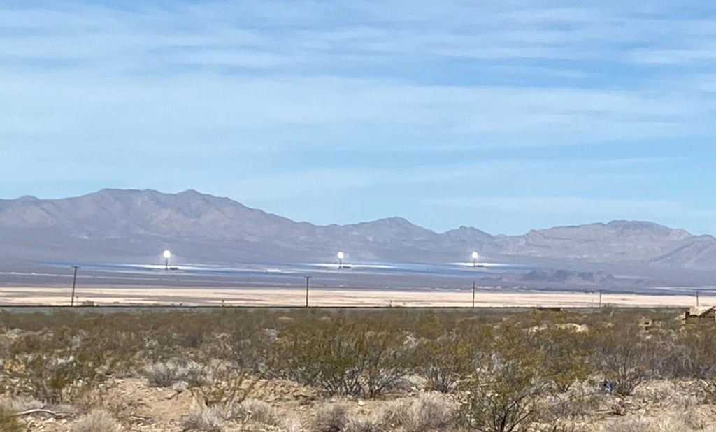
Another cool thing about Nipton is that is close to the Ivanpah Solar Power Facility, a 392 megawatt power plant that uses 173,500 heliostat mirrors to focus solar energy on three towers that generate steam to drive turbine generators. It’s pretty surreal to be standing in the Mojave Desert, surrounded by scrub and Joshua trees, and to see these three towers glowing white hot in the distance, almost too bright to look at.
Maybe I’ll write more about my Nipton adventures in a future post, but for now I want to describe the lighting effects that I created for Fly By. The controller hardware and LEDs are described in detail in this previous post.

The challenge was that until I drove down to Nipton, I had never actually seen the Manta ray – just a few photos of the exterior. In my last post I said “The Manta isn’t huge…” because my little brain wasn’t able to translate “24 feet tall” to this absolutely gigantic structure towering over my head. I was very happy to learn that I’d only have to climb halfway up to install the controllers; we hired a local guy to do the truly scary work at the top.
To facilitate future firmware and script updates, I installed the master controller and the two “remote” controllers close to each other in the belly. The master controller (FLiC board) drives 4 LED strips in the body, and the two SLiC boards drive 5 LED strips in each of the wings. Fortunately, all of the cables that I pre-fabricated were long enough to reach the strips. I zip-tied the two power supplies to a flat section of the steel frame, for the “bonus heat sink” effect.


OK, enough about the hardware; back to the lighting effects! I didn’t get much input from the artist, and I knew lot of experimentation would be needed, so I created a very crude mockup on my garage floor. I didn’t know exactly how long the strips would need to be, so I didn’t cut them yet. And I didn’t have enough room to spread the wings out to the full 90º…but close enough!
Many lighting effects for LED strips are inherently associated with the physical characteristics of a linear strip, e.g., colors and patterns that travel back and forth across the length of the strip. That’s perfectly appropriate in many situations, but can be constraining when there’s need for animating effects that suggest motion in a direction that’s not aligned with the LED strips. For example, the 5 strips in the Manta’s wings run from the wing root to the tip. But creating a “swimming” effect requires the colors/patterns to flow orthogonally to the strips, and requires tight synchronization across the strips.

One approach to remove these constraints is to use a 2-dimensional matrix of LEDs where the color/brightness of each LED in the matrix is derived from a dynamic video source. An extreme example of this is a high-definition TV, but multiple rows of conventional LED strips (or custom LED array boards) can be used to create very cool effects. The downside is that a huge number of LEDs are required, and cost/power considerations prevent this approach from being used for large-scale projects like Fly By.
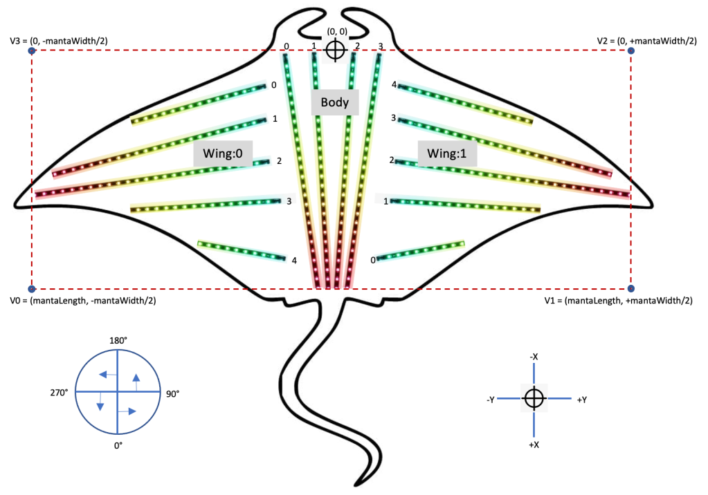
The approach that I used for the Manta falls somewhere in the middle. The key concept is that the physical position, orientation and density of the LED strips are decoupled from the spatial characteristics of the lighting effects (direction, speed, etc). For each frame update (typically 10ms for my projects), a pixel mapping function is applied to each LED strip pixel to determine its color/brightness for the duration of that frame period. The mapping function is given information that allows it to determine the 2-dimensional (x, y) position of each pixel. Although the LED strips in the Manta follow some curved interior beams, I used the simplifying assumption that they were basically straight. So the only information needed for the mapping function was the following:
- (x,y) position of the first pixel of each strip relative to a reference point in the middle of the Manta’s head
- Number of pixels in each strip
- Pixel density of the strips (LEDs per meter)
- Angle of the “straight” strip relative to the central body axis
Below is a diagram I used to define the coordinate system used for both the LED strips/pixels and for the animation effects:
So the information above defines the physical location of each pixel, but this is completely independent from the actual animation effects, at least until the pixel mapping function ties them together. The animation effects are created using virtual “objects” that exist in (and can move around in) the same coordinate system as the pixels. A very simple example is an effect I’ll call Circle, where the script-based invocation of Circle includes several parameters: a color/brightness value, an (x,y) center position, a radius, and something I call the ramp distance. The “ramp” is a function that has a value of 1.0 anywhere inside the radius of the circle and decreases linearly until it reaches 0.0 at a distance (d) from the circle’s center of d ≥ (radius + rampDistance).
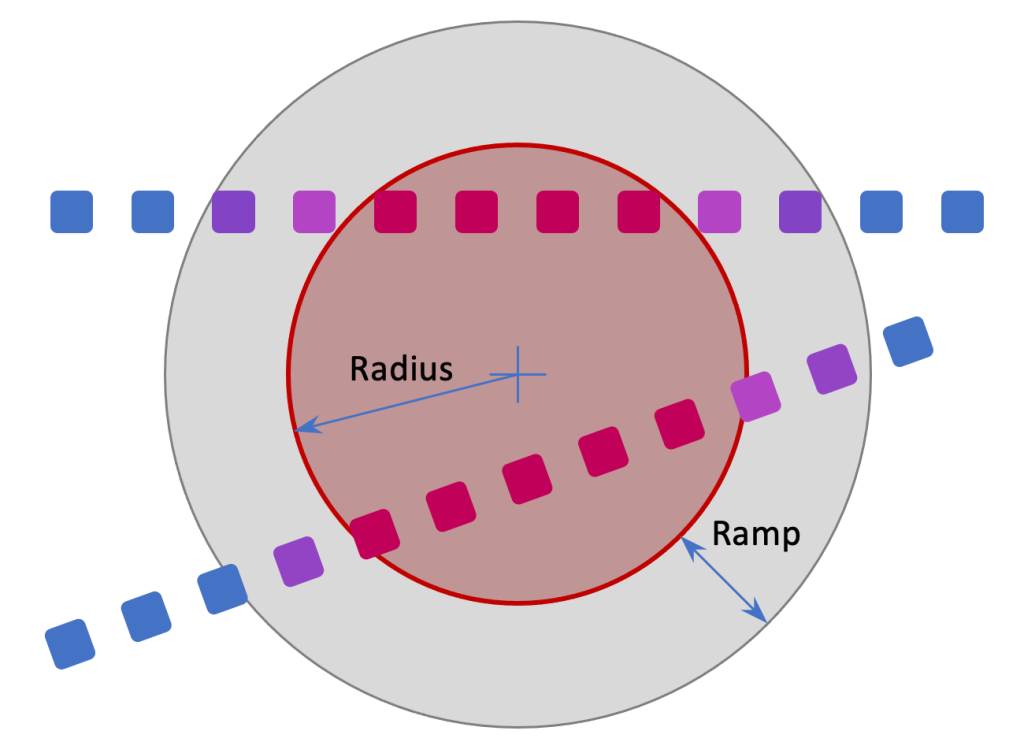
For each animation frame and for each pixel, the pixel mapping function evaluates the “influence” that the Circle effect has on the pixel. If a pixel is further away from the circle’s center than (radius + rampDistance), the existing color/brightness of the pixel is not changed. If the pixel is inside the radius of the circle, the pixel is changed to the new color/brightness specified by the Circle effect’s parameters. If the pixel is outside the radius but within the distance (radius + rampDistance), a new pixel color is computed using linear interpolation between the previous pixel color and the Circle color parameter, where the ramp function value (0 – 1) is used as interpolation weighting. If you’ve read my previous posts, you may remember that I use the HSI color space (similar to HSV), and this makes interpolation relatively easy.
Now if I haven’t lost you yet, you should be able to see that it’s pretty straightforward to animate the Circle effect, by creating additional parameters to specify the direction and speed of motion of the circle’s center point. A new center point is computed for each frame, before the pixel mapping function is applied. As shown in the Manta coordinate system diagram above, it’s useful to define a “bounding box” to constrain the range of the animation functions. For example, the Circle effect could be terminated when the circle’s center point travels (radius + rampDistance) past any of the bounding box edges. Even better, the circle could be “bounced” off the bounding box edges based on the incident angle.
The possibilities with this approach are pretty endless, but I only had time to implement a few effects for Fly By. The first is called Wipe: it changes the color of the entire Manta as if the color were being applied by a giant squeegee. The Wipe effect has four parameters:
- Start time in seconds (relative to t=0 when the script is started)
- Wipe color (HSI hue, saturation, and intensity)
- Wipe angle (0 – 360 degrees, relative to the body centerline)
- Duration in seconds (which indirectly specifies the wipe speed in conjunction with the bounding box dimensions and the wipe angle)
Here’s a demo video of the Wipe effect:
The virtual object in this case is a straight line, at the specified orientation angle, with an initial position touching the bounding box. The edge of the ramp is defined by another line that is parallel to the wipe line, separated by the ramp distance. As the wipe line is moved, the parallel ramp line trails behind it. The speed of the wipe effect is computed so that the trailing ramp line just reaches the far side of the bounding box at the end of the specified duration.
Another effect I created is called Pop. It’s similar to the Circle effect described above, except that the circle radius increases while the center position remains fixed. My goal was to make this effect look like a single-color fireworks shell exploding, leaving a new color behind (hmm, maybe more like a paint bomb). Instead of moving the circle radius at a constant speed (which wouldn’t look very realistic), I defined three phases of motion using the equations of Newtonian physics. In the first phase, the radius is increased (from zero) with high acceleration. In the second phase the radius continues to increase, but is subjected to a sharp deceleration. In the third phase the radius increases at a constant, relatively low, velocity until the end of the effect duration.
In addition to the start time and color, the Pop effect has a parameter that defines the (x,y) starting position of the pop. The acceleration, deceleration, and velocity parameters are currently defined as firmware constants, but I’ll probably make these script-defined in future releases. I’m not completely happy with the results so far, and I’ll continue to improve this effect. Here’s the current demo video:
As I said earlier, this approach allows the animated effects to be defined and implemented independently of the actual LED strips positions and orientations. But I did create some effects that are aligned with the strips. The Flow effect changes the color of successive LEDs in a single strip or a group of adjacent strips. As with the other effects, there is a ramp function that enables interpolation between the current and new colors, creating a smooth transition as the ramp “flows” down the strip.
I also created some modulation effects that allow the brightness (not the hue or saturation) to be varied as a function of time and the position of an LED within a strip. The first of these is the Wave effect, which imposes a traveling sine wave pattern on the existing color(s) of a strip. It is controlled by the following parameters:
- Start time
- Duration
- Wavelength (length of a single sine wave cycle in mm)
- Speed (linear speed of the traveling wave pattern in mm/sec)
- Amplitude (maximum amount to vary the intensity component of the current HSI color
This effect can be used for many different purposes, but for Fly By I used it on the body to convey a sense of forward motion through the water. To create a smooth transition. at the beginning and end of the effect, I define a time-based (not position-based) ramp function that slowly ramps up and down the sine wave amplitude (with a 5 second default).
The SWave effect is similar to Wave, except that it creates a standing wave pattern. It uses a frequency parameter instead of the Wave effect’s speed parameter. I used SWave for the Manta’s wings to suggest a swimming (flapping?) motion. These effects could use more tuning, but here’s a video that demonstrates the Flow, Wave, and SWave effects.
One cool byproduct of this approach to animation is that many of the effects can be used simultaneously in combination. The simplest example is to keep one of the wave/modulation effects running while new colors are being flowed, wiped, or popped in. I haven’t done this yet, but I could have defined multiple instances of the Pop object so that I could have simultaneous/overlapping explosions of different colors originating from different positions. The pixel mapping function just needs to keep track of the sequence of the pops in order to layer the colors appropriately.
What’s Next?
The artist (Peter Hazel) and the new owners of the town (and all the art) are pretty happy with the results of the new lighting installation on Fly By. There’s a very good chance that I’ll be going back to Nipton to install lighting in other artworks, some of them much larger than Fly By. But for the immediate future, Peter and I need to get cranking on this year’s Burning Man sculpture, a huge glass-and-steel Mako shark that I described in previous posts.
For the next post on this blog, I’m contemplating an article describing the software architecture that I use to achieve the effects described here. Another possible topic is the weatherproofing techniques I used for Fly By. But I’m completely open to suggestions, so feel free to suggest something.
Special message from the publisher/editor/writer/me:
I see you out there! The WordPress stats tell me that about 150 people a week are reading at least one of my blog posts. But very, very few people leave comments. So I want to encourage you to leave feedback or ask questions, either on the blog page or by emailing me at keith@electricfiredesign.com. Thanks for reading!

Massive acheivement, well done you. The true test will be just how maintenance free the sculpture will be over the years.
Did you pick up on what to look out for based on how the other sculptures had faired?
LikeLike
Thanks! Actually none of the other sculptures currently in Nipton have any significant lighting, so not much to learn there. The Manta did have a lot of lighting installed (which I replaced completely), but it was a real train wreck and apparently not intended for long-term operation. IP65 LED strips that were severely discolored and fragile. IP65 DMX floodlights connected to indoor power strips and extension cords!
I have some extra equipment left over from the Manta project, so I plan to install some in my backyard here in Reno, Nevada. I’ll monitor how it fares over the coming summer (temps in the mid-to-high 90’s) and next winter (down to low 10’s with some snow). In addition to the LED strips themselves, I’m curious about the connectors and wiring.
LikeLike
Did you replace the IP65 strips with IP67 strips (enclosed in silicone sleeves)?
LikeLike
I replaced them with IP68 strips, which have a silicone sleeve (like IP67) that is filled with silicone. These are described in the previous post, Manta Ray (Fly By) Update #1 (https://electricfiredesign.com/2022/05/19/manta-ray-fly-by-update-1/)
LikeLike
Wonderfully informative. So informative that I’m going to read it again tomorrow. Super advanced from what I’m doing with smallish LED art projects but the subject matter resonates. Your writings are a way for me to gain knowledge and be ready for my next project. So thanks! Keep it coming. And fascinating story about Nipton.
LikeLike
Thanks very much for the feedback, Daniel!
LikeLike
Thank you for sharing this Project 🙂
Greetings from Germany!
LikeLiked by 1 person
You’re welcome! Thanks for the feedback!
LikeLike
Wow, the manta ray is huge! It doesn’t seems like that until you see the photo with the guy working on it.
The effect achieved is amazing, thanks for sharing!
LikeLiked by 1 person
I have been reading your blogs for sometime now. Finally in the process of making a few boards similar to yours (hope that is Ok). I’m planning a water show with lights in my backyard, as well as for Christmas lights in the front yard. I have one small tree that I made last year and will update with the new hardware. The Manta Ray is awesome and the lighting effects you have created are spectacular. I learned a lot from reading your blogs. Thank You so much for taking the time to go into so much depth with your ongoing Projects.
LikeLike
Hey Bob, thanks so much for the nice feedback! I really appreciate that!
Please let me know if there are any specific topics or questions you’d like me to cover in future articles. And no issues with using any of my ideas/designs; in fact, I’ll give you schematics, board layouts, code, etc. if you ask.
Good luck with your projects!
LikeLike
Thanks for sharing! Fellow burner here and just started my LED adventure BUT this has inspired me AND made me thing of an interactive component for participants to be able to control the lighting as they wish.
LikeLike
I’m really happy to hear that you found some inspiration here – that’s why I do it! Good luck and have fun on your journey!
LikeLike