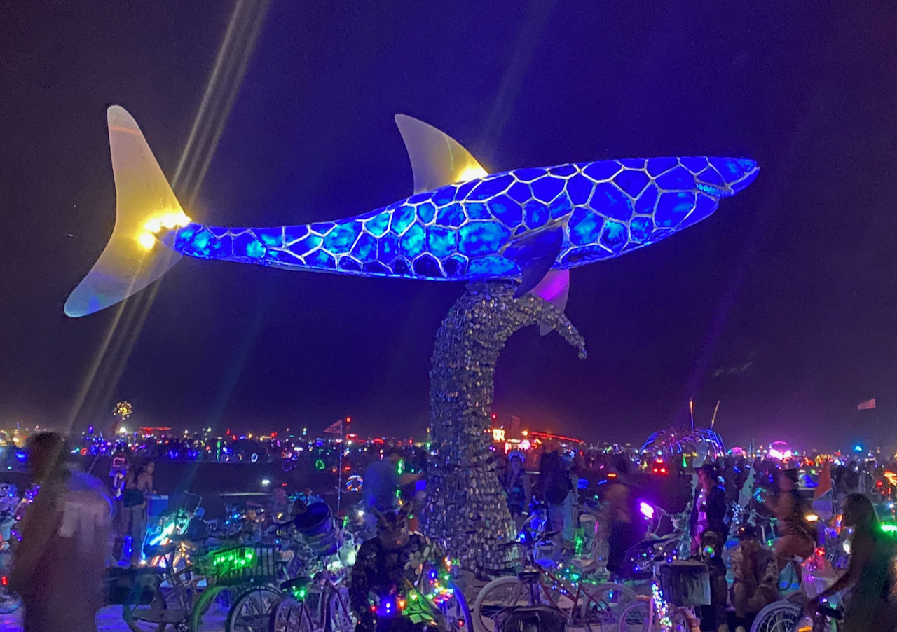
I just returned from Burning Man, the annual event of epic proportions in the Northern Nevada desert. In case you haven’t seen my previous posts (like this one, and this one), I’ve been working on the lighting for a large glass-and-steel shark sculpture created by artist Peter Hazel. With a lot of dedication and sweat from a team of about 10 talented artisans, the sculpture was successfully exhibited to the ~80,000 (temporary) residents of Black Rock City this year.
The primary goal of this post is to describe the design and implementation of the lighting system for the Shark. But the process of creating the sculpture itself was pretty interesting, so I’ll spend some time describing that first.
The Sculpture

Peter started with some simple sketches, and then created this rendering that was submitted to the Burning Man Arts organization, and also used to guide the build process.

Next he sculpted the basic shape of the body from a huge chunk of Styrofoam, adding cardboard fins to fine-tune the shapes before committing to the fabrication of stainless steel fins. He started sculpting with a hot wire device to melt the Styrofoam, but abandoned that for an electric chainsaw. I’m glad I didn’t have to clean up the mess!

A channel was then carved into the shark’s belly to accept a square cross-section steel beam that would form the central structural element of the sculpture.
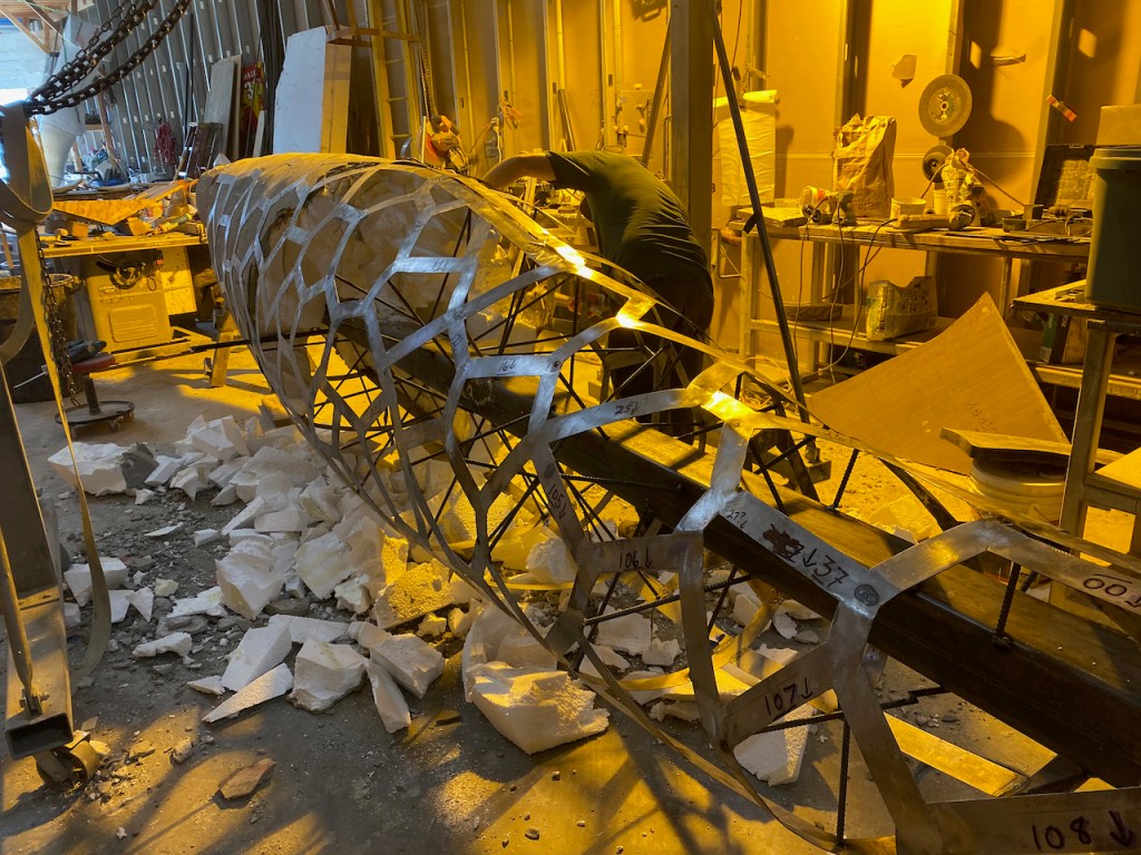
After applying a thin layer of mortar to create a harder, heat-resistant surface, steel strips were welded together to form what I call the “exoskeleton”, following the contours of the body.

Then the fun part! The mortar-coated Styrofoam was incrementally cut away, and pieces of steel rebar were welded between the core beam and the exoskeleton.
During this phase, other steel components were welded in place to provide mounting brackets for the fins, crane lift attachment points, and a “socket” that would fit over the square base/mounting beam.
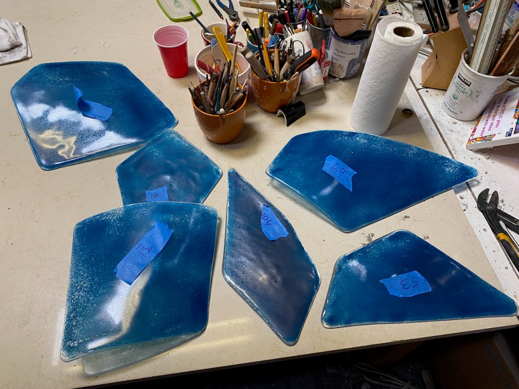
Going back a step: before the mortar/foam was removed, Peter created individual molds for each of the 146 “plates” defined by the exoskeleton. He used these molds to fuse and slump blue glass to the desired thickness, shape and contour. I’m a bit hazy on the details of this process, but that’s fine with me.
The last step of creating the shark’s body was to attach the glass plates to the exoskeleton using silicone adhesive. But instead of fastening them directly to the metal, the plates were attached to 5/8″ thick clear glass spacer blocks, creating the impression that the plates are floating above the exoskeleton.
The Lighting

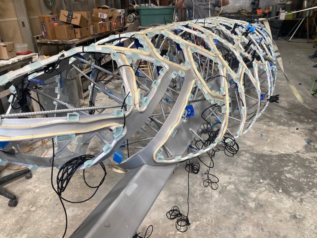
Peter’s primary request for the lighting design was to intensely illuminate the portions of the exoskeleton that would be exposed in the narrow gaps between the glass plates. But in doing so, he wanted to avoid any visible LED pixels, what he calls “hot spots”. After several iterations, we decided to use sections of non-addressable (i.e. “analog”) white LED strips wrapped around the spacer blocks for each glass plate. Because of the curvature of the body, the strips didn’t always lay quite flat against the surface. But since the plates overhang the spacer blocks, they mostly hide the LED strips from direct view. Good enough.
The back sides of the silicone-sleeved strips are glued to the spacer blocks using a type of fast-drying cyanoacrylate (CA) glue that is optimized for materials like silicone. This glue works very well, but is quite expensive. We also discovered that regular silicone caulk-type adhesive works well, but was impractical due to the long curing time.
I selected natural-white FCOB (flexible chip-on-board) strips from BTF-Lighting. These 24v, 10mm wide strips have 528 LEDs per meter, making the strip look like a continuous band of light under normal viewing conditions. You can get non-waterproof (IP30) versions of these strips from Amazon and other distributors, but this outdoor application required full weatherproofing. I sourced an IP68 version directly from BTF-Lighting for a very reasonable price, even when shipping was included. They make an IP67 version that is essentially the IP30 strip encased in a molded silicone sleeve, but they didn’t recommend this for a long-term outdoor application. The IP68 version has the outer sleeve filled with silicone, but still has very good clarity and flexibility. The silicone filler also seems to make the strip much more durable and resistant to physical. damage.

For several reasons, it was necessary to cut the LED strips into individual segments according to the unique size of each glass plate. This required a somewhat elaborate process that I spent considerable time optimizing. The steps for each LED segment were:
- Measure and cut the segment with a sharp box knife at the designated cut points that are about 45mm (1.8″) apart.
- At one end, score the silicone sleeve with the knife and peel/scrape away the silicone filler to expose the copper pads (+24v, GND). Thoroughly scrape and clean the copper pads with isopropyl alcohol to remove all bits of silicone.
- Prepare a 180mm (7.1″) section of 20 AWG 2-conductor cable for attachment to the LED segment: strip jacket and wire ends, tin the wire ends.
- Tin the copper pads on the LED segment. This is easier with a relatively hot soldering iron. I set mine to 850ºF (454ºC).
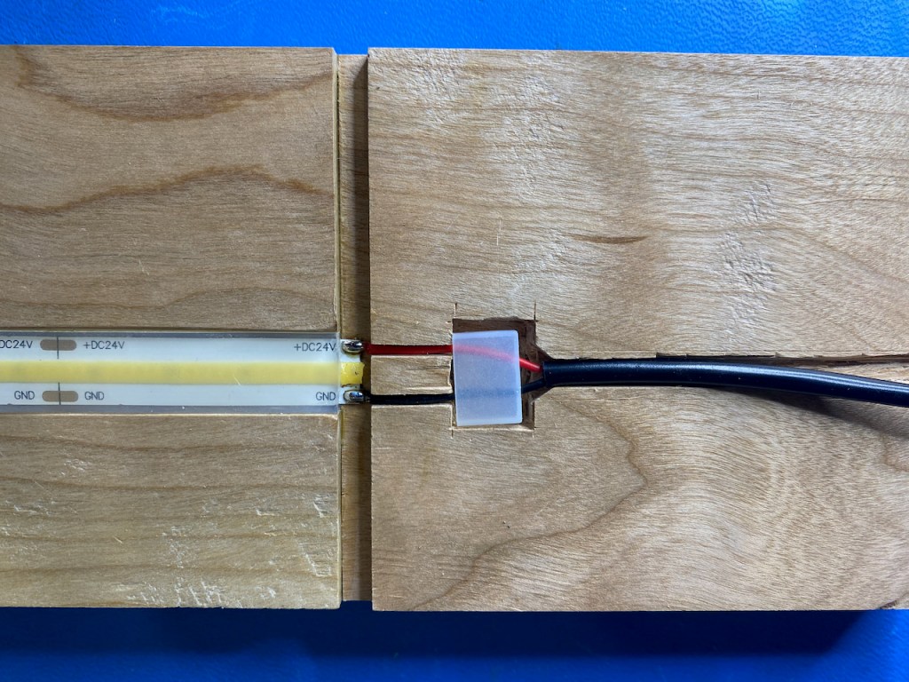
- Thread the two wires through a silicone end cap and solder to the LED segment. Based on my request, BTF-Lighting provided me (free) with 300 end caps, half of them with holes for wires. To make this step easier, I made a wood fixture (photo below) that holds the LED strip, the wires, and the end cap in alignment during soldering. Better than having three hands!
- Fill the end cap 1/2 to 2/3 full of silicone sealant and press it onto the end of the strip, squeezing and wiggling to eliminate air pockets, and then wipe off the excess. I used this electronics-grade sealant to avoid the possibility of long-term corrosion of the copper. Rather than try to directly inject the silicone from the large tube, I transferred small amounts into a plastic syringe with a smaller tip.
- Using the same method, apply a closed-end cap to the other end of the LED strip segment.
For most of the segments, I added a piece of heat shrink tubing to cover the short, exposed section of wires between the end cap and the cable jacket. But this turned out to be a bad idea as it caused a stress point that occasionally resulted in the pads tearing when the cable was bent during installation. In the future, I’ll look for a way to make a stronger mechanical connection between the cable jacket and the end cap, as is the case for the factory installed cables.
For this project there was no intent to individually control the white LED strip segments; we just needed to control the brightness of the entire set. The average length of the 146 segments was about 1.4m (4.6′) each, so we used a total of about 204m (670′) of LED strip. At maximum brightness, the strip power consumption is 10 W/m or a total of 2040W. The maximum current is therefore 2040W / 24v = 85A. In theory all of the segments could be wired together in parallel and controlled with a single high-current driver. But that approach has lots of practical challenges, so instead I divided the segments into 24 groups, each containing 6 (or sometimes 7) LED segments. This brings the per-group maximum current down to 3.5A, something much more manageable. Each group was wired as shown below.

Each of the splice connections was soldered and sealed with two layers of heat shrink. tubing.
OK, enough about the exoskeleton lighting; now on to the internal color lighting that backlights the glass plates. I had originally planned to use small RGB floodlights, but after seeing how cramped and crowded the internal space would be, I switched to using WS2815 addressable RGB strips, mounted along the length of the “core” beam. Note that IP67 and IP68 LED strips do not have an adhesive back, so mounting was done with zip-ties.
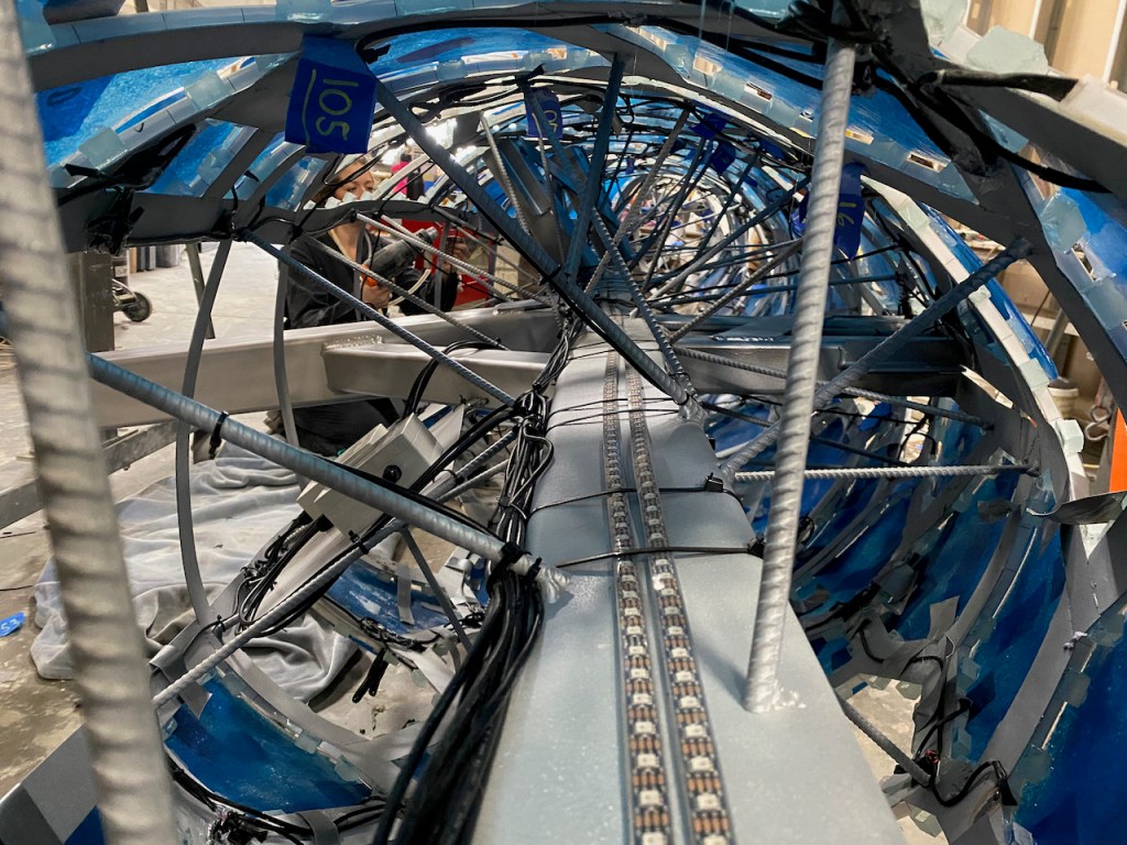
I used two strips for each of the core beam faces. Since the shark is about 7.6m (25′) long, I offset each of the 5m strips on each face so that there would be maximum brightness in the (fatter) center and less brightness in the narrower head and tail sections. Since the strips didn’t need to be cut, I ended up using the factory-installed 4-pin connectors. (like these). On each face, I mounted the input end of each strip (connector end) toward the center of the body, meaning that the “data flow” of the strips ran in opposite directions. This and the offset locations of the strips were handled by the software, as described later.
Controllers

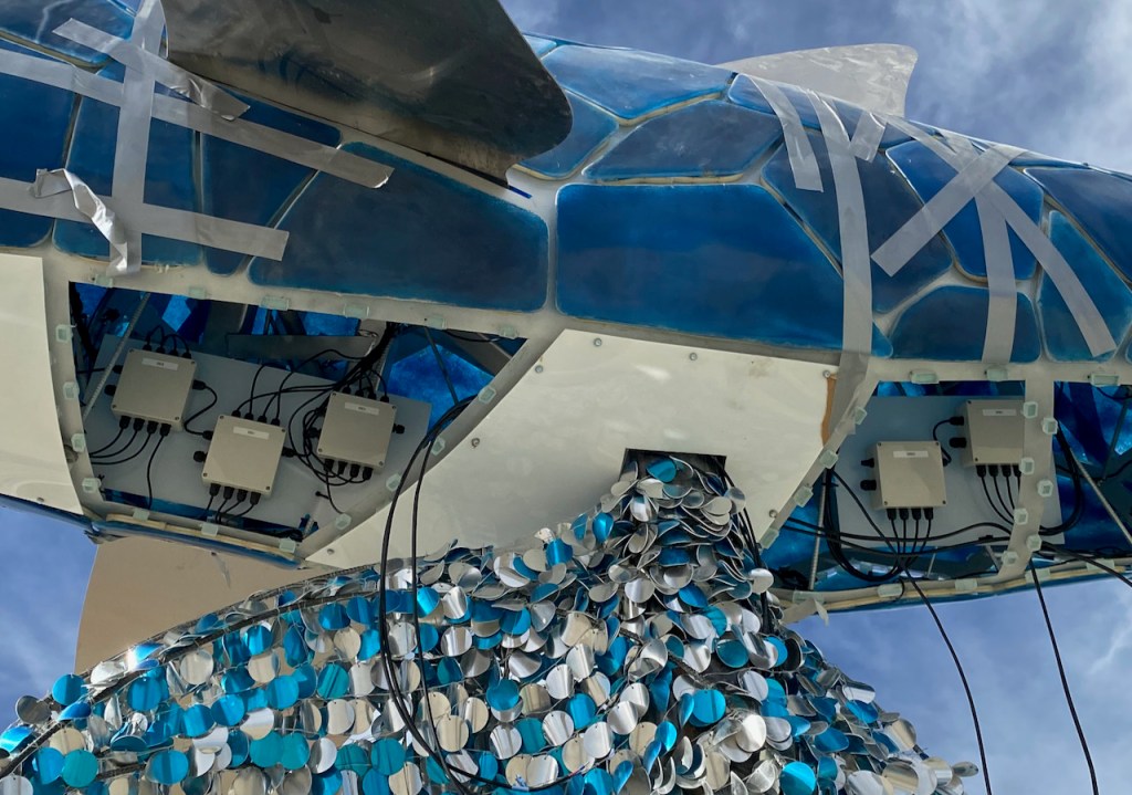
The controller architecture is similar to that of the Manta Ray (Fly By) project described in this blog post. In this case I used a stripped-down version of my FLiCr board (blog post #1, post #2) as a master controller that issues commands (via the RS-422. serial SLiC Bus) to other “remote” controllers that handle the white “Exo” LEDs and the RGB “Core” LED strips. Unlike the Manta project, I didn’t use the master controller to also drive any LEDs, since I wanted to mount this enclosure at the base of the shark’s pedestal for easy access. The other controllers were mounted inside the shark, accessible via removable acrylic panels on the belly (with a really tall ladder or a lift).
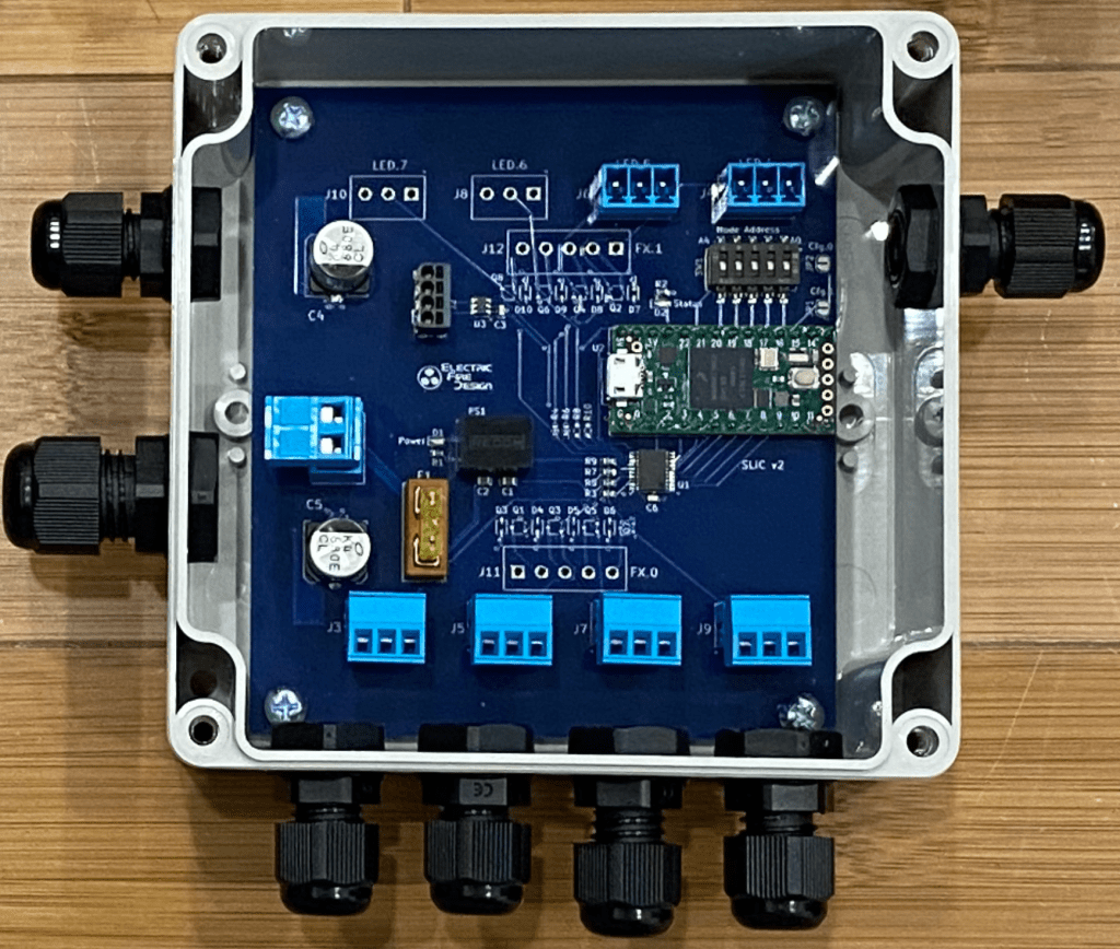
To drive the eight Core LED strips, I again used the SLiC (v2) board, with each of two boards configured to drive four addressable LED strips. Divided the 8 full-length strips across two boards kept the current levels reasonable. At max brightness each strip draws about 3.6A at 12v, so four strips is 14A, close to the maximum that the board was designed for.

Although the SliC v2 board can also be configured to drive analog LED strips (like the Exo lights) using PWM outputs, the connectors used for the PWM outputs were not optimal for this application. So I created a minor variation, the SliC v3, that provides eight high-current PWM outputs with a separate 2-pin screw terminal connector for each output. Three of these boards drive the 24 Exo LED groups, with each output driving 3.5A max and each board handling up to 28A. Well…the board really can’t do that on a continuous basis, so I knew that the maximum brightness/current would need to be capped by the software. But that wasn’t a problem: since these LEDs are so blindingly bright, I never came close to needing to run them at max brightness, even on a transient basis. More on that later.
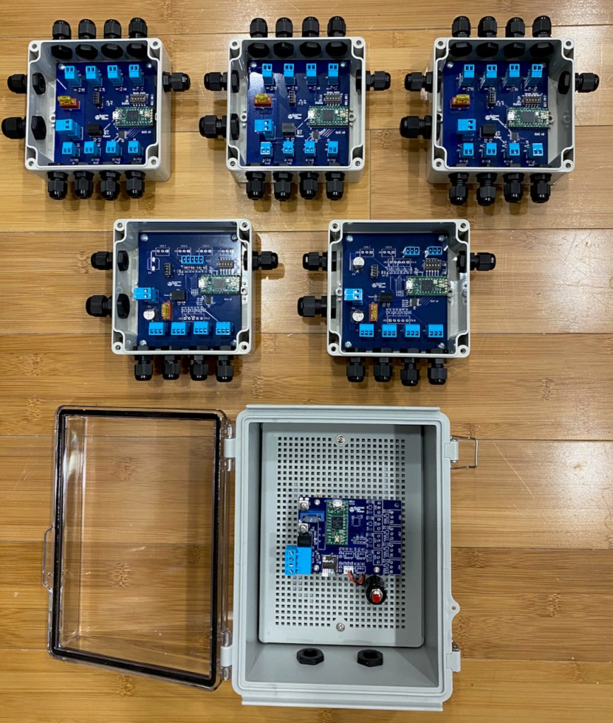
Here are some controller family photos, in the lab and in the belly of the…shark.
Power Supplies

Due to the compressed project schedule, I needed to select and procure the power supplies before I knew the exact quantities (and power requirements) of the Exoskeleton LEDs. I decided to use a separate 24v supply for each of the three Exo controllers, and I selected the Mean Well HLG-480H-24. This IP67-rated supply can deliver 20A continuously at ambient temperatures up to 50ºC (122ºF). At the time, I assumed that each board would need no more than 16A max continuous (2A per output), meaning that the supply would never be driven to more than 80% of its maximum rated load. That’s a reasonable safety margin to ensure long-term reliability. Previously I noted that each board (and power supply) would need drive 28A to achieve maximum brightness. So to keep the power supplies below 80% load, I need to constrain the LED brightness (based on PWM duty cycle) to less than 16A / 28A = 50% duty cycle. For brief periods I can go up to at least 20A / 28A = 71% duty cycle, possibly higher. Plenty bright.
For the Core (WS2815) LED strips, I chose a 12v power supply from. the same Mean Well family, the HLG-240H-12. This supply can deliver 16A continuously, and I used one for each of the two Core controller boards. Since I need 14A at full brightness, the power supply will be running at 14A / 16A = 88% maximum continuous load. Although I typically run the Core strips at full brightness, the animation effects (see below) result in many pixels being at less-than-full brightness, so the margin is actually much higher.
I still plan to write a separate article about weatherproofing of lighting-related electronics, but I’ll touch on some of the topics here. One of my goals was to minimize the number of connectors that are located outside of a weatherproof enclosure. Weatherproof enclosures are relatively inexpensive compared to the large number of individual weatherproof connectors that they can eliminate. This approach also reduces the number of possible failure points.
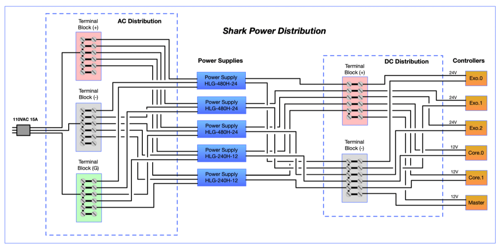
So the challenge of the power supply subsystem design for this project was to provide the following:
- Distribution of 110 VAC from a single receptacle plug to five separate power supplies.
- Connection of the Ground (GND) output of all five power supplies to a common ground reference point.
- A tap from one of the 12v supplies to provide +12v (and GND) to run the master controller (only ~200 mA).
- Three 24v/GND and two 12v/GND outputs that support the ~5m (16′) cable runs from the power supply subsystem (mounted in the pedestal) to the Exo and Core controllers mounted inside the shark.
This was accomplished with the wiring design shown below:
And here are photos of the AC Distribution box, the DC Distribution box, and the complete power supply subsystem assembly/panel:

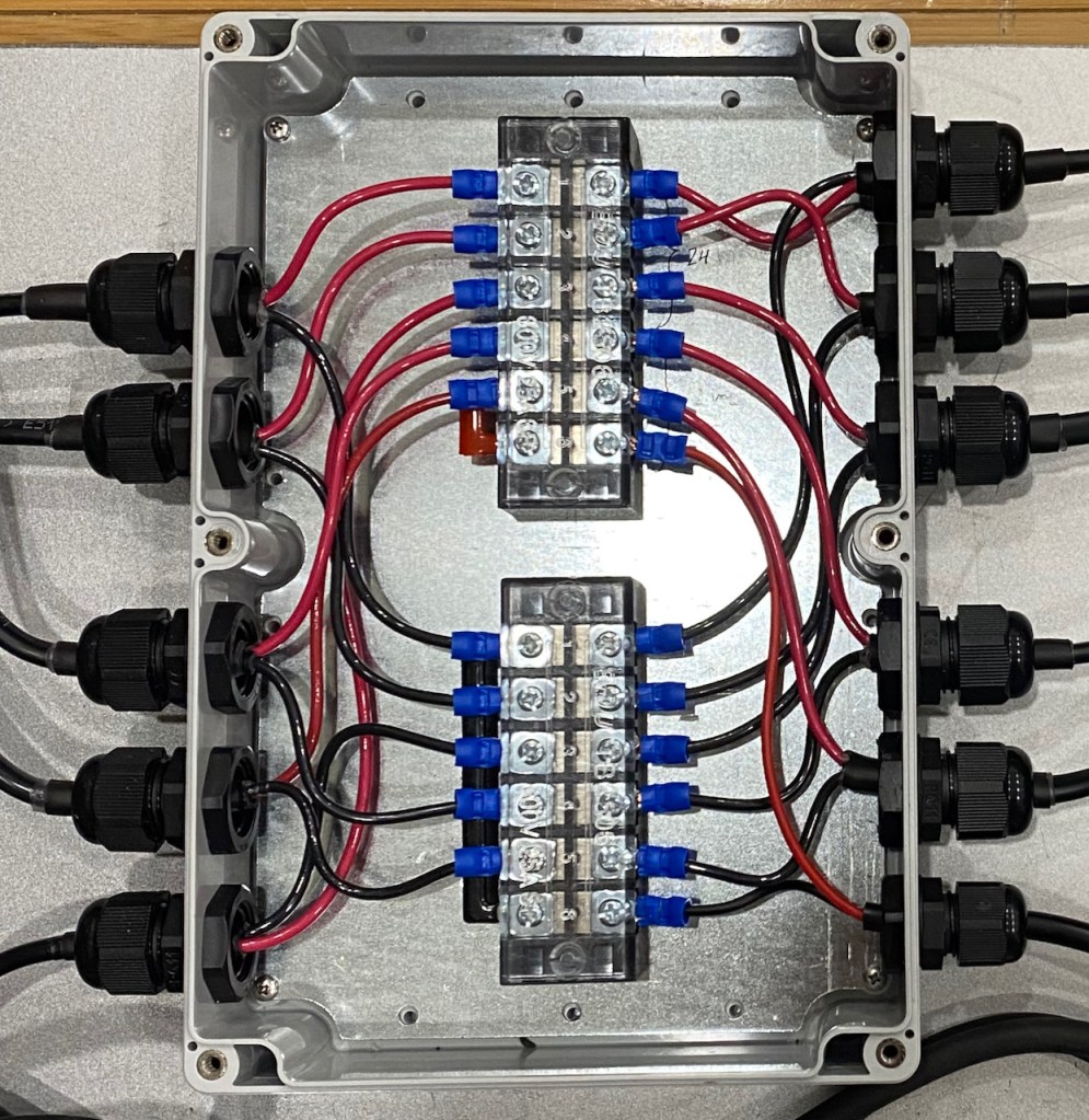
The IP68 enclosures worked well, as did the really inexpensive terminal blocks. The cable glands worked OK, but the mounting threads weren’t quite long enough to provide a rock-solid attachment to the 3.05mm (0.12″) thick enclosure walls.

All of the DC-side connections were made with 14 AWG 2-conductor, UV-resistant cable, including the long runs up to the shark body. The only issue was that this somewhat stiff cable has an oval cross-section, which prevents a perfect seal in the cable gland. I mitigated this my adding a short section of heat shrink tubing that added some compliance when tightening the gland.
The factory-installed power supply cables weren’t long enough, so I solder-spliced in additional cable as needed to reach the distribution boxes. Note that the 24v supply outputs were split between two cables, so I joined these at the splices.
Lighting Effects
I had very few opportunities to test any lighting effects on the actual shark, so I had to guess at what was going to look good, while also keeping it simple due to schedule pressures. And I’ve learned that it’s practically impossible to do any significant amount of design/coding work while at Burning Man — just too many distractions! So what I describe below is just the first of many subsequent post-Burn revisions.
For the white Exoskeleton LEDs, the basic mode is a slow pulsating effect that modulates the brightness based on a parameterized sine wave. This effect is controlled by commands in the FireScript lighting effects scripting language that I described near the end of this older post (the details have changed somewhat since then). For this effect, a typical command looks like this:
20, PULSE, Exo, level=0.2, freq=0.3, ampl=0.1, rampDur=10
This means: “At 20 seconds after the start of script execution, apply the PULSE effect to the lighting element named “Exo”, with the following parameters”. The “level” parameter defines the average brightness of the effect (i.e. the Y axis or baseline of the sine wave), as a percentage of full brightness (1.0). The “freq” parameter defines the sine wave frequency in Hz. The “ampl” defines the absolute value of the sine wave peak relative to the baseline. So in this example, the LED brightness will vary between 10% and 30% brightness at a 0.3 Hz rate. These are the values that we actually ended up using, and is reflected in the photos and videos below.
Note that the “level” parameter actually defines a “perceived brightness” level, not a PWM duty cycle. Due to non-linearities in the perception of brightness by the human eye, a “gamma correction” formula is used to translate the linear brightness (“level”) scale to corresponding PWM values: PWM = (Brightness)(gamma) . For many LED projects, including this one, a gamma value of 2.0 is used. So a brightness level of 0.3 translates to PWM = 0.32 = 0.09, i.e. a PWM duty cycle of only 9%. That means that at the upper peak of the sine wave, each Exo power supply is only putting out 28A * 0.09 = 2.5A. Nice!
The “rampDur” parameter enables smooth transitions between the parameter values of consecutive PULSE commands; it defines the amount of time (in seconds) over which the transition is to be applied. RampDur=0 means that the effect parameters are applied immediately with no transition. So consider this sequence:
15, PULSE, Exo, level=0.05, freq=0.3, ampl=0, rampDur=0
20, PULSE, Exo, level=0.2, freq=0.3, ampl=0.1, rampDur=10
At t=15 seconds, the LEDs will all turn on (immediately) at brightness level=0.05. Because ampl=0 there will be no sinusoidal variation, but the baseline frequency is set to 0.3 Hz. At t=20 seconds, the brightness level will gradually increase from 0.05 to 0.2 over a period of 10 seconds. Simultaneously, the sine wave amplitude will increase from 0 to 0.1 over the same period, with the sine frequency unchanging at 0.3 Hz. The same approach can be used to gradually change the frequency, either separately or in combination with the other parameters. The basic idea to is be able to change the pulsating effect during the course of script execution (usually between 1 and 5 minutes duration) very smoothly without any jarring “steps”.
Two FireScript effects are defined for the addressable RGB Core LEDs. The FLOW effect causes a new color to “flow” down the length of the shark, starting at the head. Here’s an example command:
50, FLOW, Core, pcolor=5 0.6, dur=10, ramplen=200
This causes palette color 5 (from a separately-defined color palette), at 60% brightness, to be flowed down the length of the shark (the Core element) over a duration of 10 seconds. The new color replaces any existing color, and rampLen=200 indicates that blending between the previous and new colors should be applied across a linear ramp function with a length of 200mm at the leading edge of the color flow. This leading-edge color blending looks good when the color hues are not too different, but causes distracting rainbow effects when the hues are very dissimilar. In these cases, rampLen=0 disables the blending.
The FLOW effect also allows colors to be specified explicitly in the HSI color space, using hcolor=<hue> <saturation> <intensity>. For more details on the use of the HSI color space, see the “Color Space Conversions” section of this blog post.
The WAVES effect causes the Core element to be brightness modulated by a traveling sine wave pattern. For example:
60, WAVES, Core, wavelen=800, speed=200, level=0.6, ampl=0.4
In this example, the sine wavelength is 800mm and the pattern travels along the shark’s length at 200 mm/sec. The average brightness is 60% and the peak deviation about the average is 40%.
The WAVES effect is intended to impart the impression that the shark is swimming forward through water, although in reality it’s a bit hard to discern given the color variations in the glass plates and the simultaneous modulation of the white Exo LEDs.
It’s important to note that the parameters of the FLOW and WAVES effects are based on the. dimensions of the shark body, not the LED strips themselves. The effect implementations in the Core controller perform a coordinate-space transformation (1-dimensional for this project), taking into account the mounting location and orientation of each individual strip. This technique is. described in more detail in my blog post about the Manta Ray/Fly By project, which uses a 2-dimensional transformation.
Ok, enough of that! What do these effects look like?
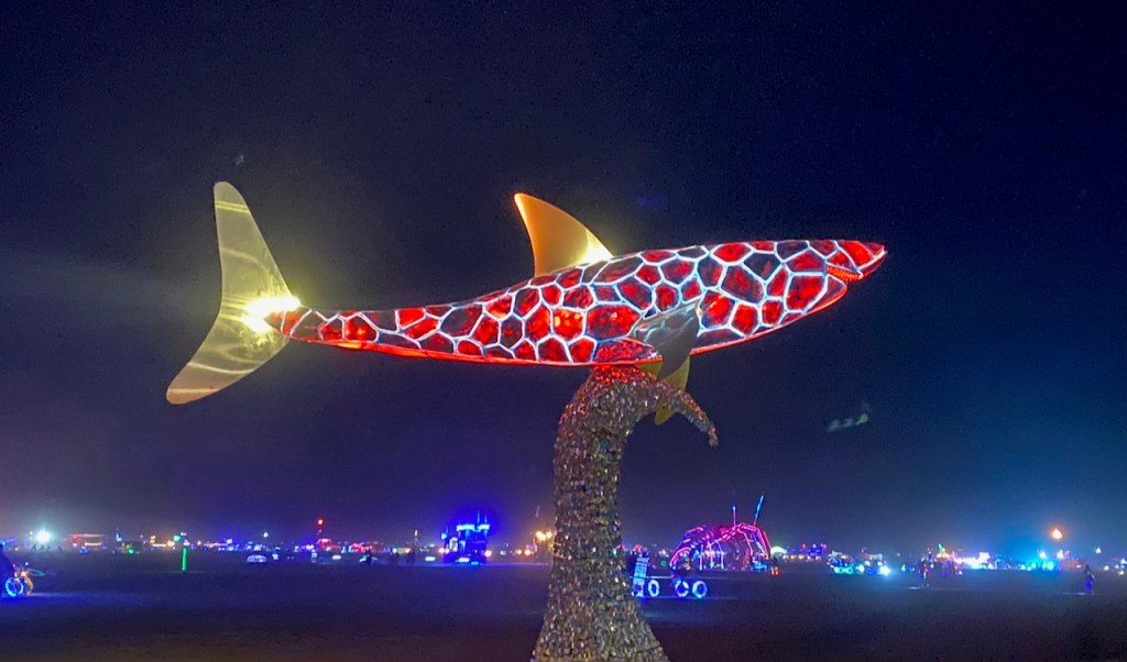
Results
I’m not the best photographer/videographer, but here’s what I got during the week of Burning Man. Maybe somebody else got some better shots?


Confessions
Well, OK, not everything worked perfectly. The Exo LEDs sometimes operated erratically and I’m 90% sure this is caused by unreliable communication from the master controller to the Exo controllers across the RS-422 serial SLiC Bus. On the Manta Ray project I used only two remote controllers, with a fairly short SLiC Bus cable from the master. This project used 5 remote controllers and a much longer cable run, with the Exo controllers at the end. I neglected to add a termination resistor across the differential pair at the end of the run, and I suspect that signal reflections caused some of the messages to be dropped. Fortunately, the commands were resent each iteration of the ~2 minute script, and the message failures didn’t occur every time. This will hopefully be an easy fix when I get my hands on it again next week.
Next?
Overall, Peter and the team were really happy with the lighting (whew!). For now, the Desert Shark will take up residence on a private lot here in Reno, within view of the Eastbound I-80 freeway entering town. I plan to create a much more elaborate script, adding some less-mellow sequences to simulate a Jaws-like shark attack. Get out of the water!

Oceans rule the earth! Thanks for the amazing art and the detailed write up, we enjoyed both! https://imgur.com/a/WdQf6zz
LikeLike
Fabulous, Keith!
LikeLike
Thanks, Neal! It was great that we were able to meet up on the playa.
LikeLike