
In this article I’ll share my preferred techniques for protecting the components of an outdoor LED lighting system from the elements: rain, humidity, dust, sunlight, etc.
I’ve been designing LED lighting systems for outdoor art installations/sculptures since 2019. My first couple of projects were for Burning Man, and my primary concern was ensuring that the lighting would continue to work over the weeklong event in the presence of searing heat, copious quantities of dust, and the remote (but non-zero) possibility of rain. I paid some attention to weatherproofing, but long-term reliability wasn’t a primary concern. Later I learned that these non-burnable art pieces had multiple lives: they often were displayed in multiple venues (art shows, public exhibitions) before being sold to private collectors. So I changed my mindset and started designing the lighting systems to last at least 10 years with appropriate maintenance.
I did a lot of research and developed a new set of weatherproofing techniques, most of which I’ve now employed in two large projects (Manta Ray/Fly By, and Desert Shark). But…not enough time has passed to tell for sure whether these techniques will provide the expected longevity and reliability. So you’ll have to use your own judgment to determine if this techniques make sense for your project.
Environmental Threats
There are multiple environmental factors that conspire to make your lighting project go phhtt, and these go beyond what you would consider “weather”. Let’s look at them individually.
Rain/Snow – Rain is usually what immediately comes to mind when thinking about weatherproofing. In addition to accommodating very intense periods of rain, designers also need to deal with rain that may be blown sideways by strong winds. Snow may accumulate on exposed electronic enclosures, and when melting, may penetrate an enclosure in ways that rain might not (e.g. melting into ventilation openings in vertical surfaces).
Humidity – In humid conditions, significant amounts of gaseous water vapor are carried in the air. When the air comes in contact with a surface with a lower temperature than the air (for example, a circuit board inside a ventilated enclosure), there is a chance that the water vapor will condense into liquid water that attaches itself to the surface. This condensation (aka dew) can even happen in non-ventilated enclosures, since most weatherproof enclosures are not completely airtight.
Regardless of whether moisture arises from rain, snow, or condensation, there are three primary mechanisms by which moisture can damage the electronics in a lighting system. The first effect is commonly thought of as a “short circuit”, but that’s a bit misleading. Pure distilled water is completely non-conductive, but rainwater typically contains impurities that make it slightly conductive. A droplet or sheet of water on a circuit board can cause “leakage” currents to flow between component leads that are not intended to be electrically connected. This can cause immediate circuit malfunctions, possibly triggering a cascade effect that leads to permanent circuit damage.
The second damage mechanism, corrosion, occurs over longer time periods. Electrochemical reactions can occur between adjacent metallic elements when water provides a conductive path between them, resulting in irreversible material degradation that will eventually result in a malfunction.
The third damage mechanism occurs in polymeric materials that can absorb water, including “plastic” component packages and epoxy adhesives. Swelling can result in warpage and mechanical stress failures. Water can also cause chemical reactions that reduces the strength of adhesives, causing debonding failures.
See this article for (much!) more detail: The detrimental effects of water on electronic devices.
Dust – Although dust itself doesn’t affect the operation of solid-state electronics, there are a few things to watch out for. Obviously, dust particles can interfere with the operation of mechanical switches, relays, or connectors that needed to be mated/de-mated over the life of the system. Fans used for forced-air cooling, in addition to increasing the rate of dust deposition, will also eventually experience performance degradation due to dust accumulation on the fan blades and shaft. A more insidious effect is that dust provides more surface area for condensation, and provides a cozy blanket in which moisture can remain trapped for longer periods.
Ultraviolet (UV) Light – Prolonged exposure to sunlight can result in deterioration of the materials in electronic enclosures, LED strips, cables, connectors, and even zip-ties (cable ties). The real threat here is that the degraded material will be more susceptible to water intrusion, leading to other types of damage described above. Zip-ties can become brittle and break. UV exposure can also result in yellowing and embrittlement of clear polymeric materials like LED diffusers.
The remainder of this article will discuss environmental protection techniques for each of the major elements of a typical lighting system. I make frequent references to the IP (ingress protection) rating of components, so if you’re unfamiliar with IP rating, this Wikipedia article will bring you up to speed. Some manufacturers use a similar NEMA (National Electrical Manufacturers Association) rating system, and this article provides a comparison between the IP and NEMA rating systems.
Power Supplies
In my experience, the selection of a particular type of power supply has a major impact on the overall weatherproofing strategy for a lighting system, so it makes sense to discuss this first.
In my early projects, I used power supplies from the popular and inexpensive Mean Well LRS family. The power output of this family ranges from 35W to 600W, with fixed output voltages between 5v and 48v.
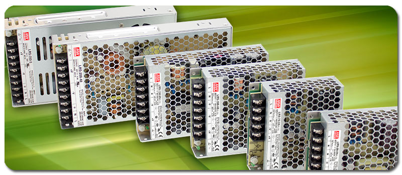
This type of chassis-enclosed power supply relies on convective air flow around and through the chassis to cool the components, and can deliver full rated power at ambient air temperatures of up to about 50ºC (122ºF). The higher-power members of the family also include a fan that automatically turns on when the temperature reaches a certain level.
Obviously this type of power supply has no protection against dust or moisture, and must be installed inside a weatherproof enclosure. But that’s a problem: an unventilated enclosure prevents the free flow of cooler ambient air through the power supply’s chassis, and this will severely restrict the amount of power that can be delivered without overheating (and eventual failure). Ventilated enclosures are certainly available, including ones with a fan to promote airflow. But these vents, even with filters, just provide an entry path for dust and humid air. Furthermore, ventilated enclosures tend to be larger and much more expensive than completely sealed enclosures (see the next section for more details).
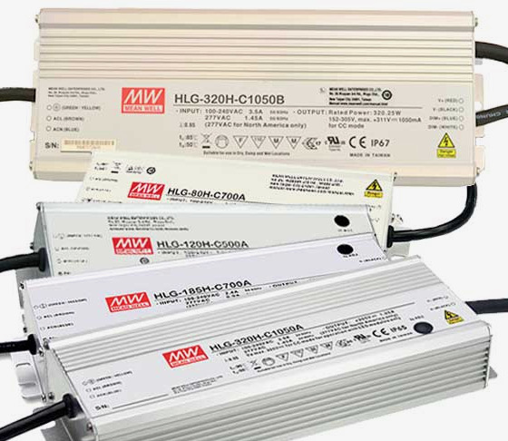
For me, the solution was to use environmentally-sealed power supplies, such as the Mean Well HLG series. These range from 35W to 600W, with voltages between 5v and 48v. These are available with a variety of features, but the fixed-voltage units have an IP67 rating. The high end of the full-power temperature range is about the same as the LRS series: 50ºC.
Although sealed power supplies are more expensive than their non-sealed equivalents, the advantage is that they require no additional enclosure. For my projects, that means that I can mount them to a metal plate or beam (typically an existing part of the art sculpture) that provides a conductive cooling path in addition to the convective path to the ambient air. This serves to keep the power supply temperature lower, which increases reliability and longevity.
One downside of sealed power supplies is that the AC input and DC output cables are pre-attached, as necessary to maintain the integrity of the seals. The cables are a bit short (300mm for the HLG series), and it is often necessary to splice in additional wire to achieved the desired length. Also, on some of the higher-power units, the DC output is split between two sets of cables, neither of which is individually of sufficient gauge to carry the full rated current. But merging these two cables as part of the splice is an easy solution.
Enclosures
When environmentally-sealed power supplies are used, additional enclosures are only needed for the controller electronics, which typically generate very little heat. In this case, fully-sealed (non-ventilated) plastic enclosures can be used. If necessary, a metal enclosure (typically aluminum) can be used for increased durability and to provide a conductive path for heat dissipation. The remainder of this discussion will focus on inexpensive plastic enclosures.
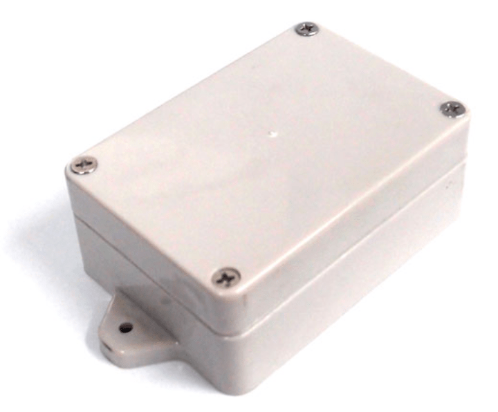
Weatherproof plastic enclosures for electronics are available from many sources in a wide variety of shapes and sizes. The fabrication material is typically ABS (acrylonitrile butadiene styrene), or polycarbonate. While ABS enclosures will be acceptable in most applications, more-expensive polycarbonate enclosures have a several advantages that may be important: polycarbonate has much better UV resistance, higher impact strength, and better machining properties. On the latter point, some types of ABS have a tendency to soften and melt when being drilled.
Most weatherproof plastic enclosures that are advertised as “weatherproof” have an IP rating of at least 65, which should be acceptable for most outdoor lighting installations that are not subject to water immersion. This level of protection is achieved by using a continuous silicone gasket that is fitted into a groove in the perimeter of either the case body or the removable lid. A continuous “tongue” shape on the opposing piece presses into the gasket when the lid attachment screws are tightened, causing the gasket to expand and form a highly water-resistant seal. Some enclosures have hinged lids, and these use dual latches to generate the required force on the gasket.
Here are some additional points to consider when selecting an enclosure:
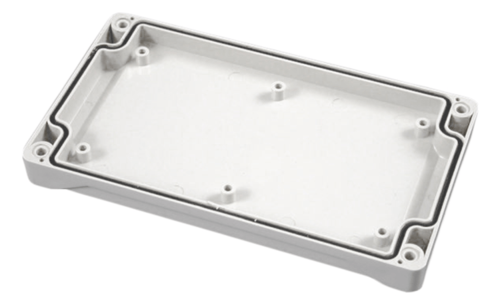
- On higher-quality enclosures, the gasket is a continuous piece of silicone that is formed to the specific shape of the box. It may be pre-installed or may require you to install it. On low-end enclosures, the gasket is a cut piece of silicone which may not be pre-formed. These are much more difficult to install.
- Most enclosures include a number of molded mounting posts in the bottom part for mounting circuit boards or other electronic components inside. However, these are not very convenient unless you’ve custom-designed your circuit board for the specific enclosure and mounting hole locations (which I do sometimes). Some enclosures provide a metal or plastic mounting plate that attaches to these holes, and can be drilled to provide mounting points for other components. Sometimes these can be purchased as an extra-cost option.
- Some enclosures have box-mounting tabs molded to the exterior of the case; on others the mounting holes can only be accessed by removing the cover.
- On most enclosures the cover attachment screws are accessed from the front side, allowing the cover to be removed after the enclosure has been mounted in your installation. This is very convenient, so beware of enclosures with cover screws on the back side of the box.
- On better-quality enclosures the cover mounting screws are stainless steel and captive, so they don’t fall out when the cover is removed. They attach to metal bushings (captive nuts) on the bottom part, allowing the cover to be removed/reinstalled many times with consistent torque. Cheaper enclosures use self-tapping screws directly into plastic posts.
- If you will be drilling holes in the enclosure to attach cable glands (see below), carefully check the internal dimensions to ensure adequate space for the large nuts, and check for the presence of molded internal ribs that might interfere.
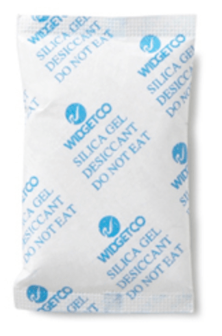
Even with sealed enclosures, it’s impossible to completely prevent the intrusion of small amounts of moisture, possibly in the form of water vapor that may condense. To mitigate possible long-term damage from this moisture, one option is to install a silica gel desiccant packet inside the enclosure. These are very inexpensive and are available in a wide variety of sizes. They can absorb up to 40% of their weight in water. The downside is that they need to be periodically replaced, possibly as part of a regularly-scheduled maintenance program (see below).
Cabling
The main environmental threat to electrical cables is prolonged UV exposure that can lead to premature aging and embrittlement of the insulating jacket. Cracking of the jacket can lead to water intrusion that will in turn cause degradation of the internal wire insulation and copper.
The best way to mitigate this threat is to use cables that are specifically designed for long-term outdoor use and are “UV resistant”. Typically this means that a small amount of carbon black, which absorbs UV radiation, has been added to the composition of the PVC material in the jacket. That’s why most outdoor-rated cables are black in color. Unfortunately, cable data sheets are difficult to track down, and are very non-specific about the degree of UV resistance of the expected cable lifetime under specific environmental conditions.
One other point to consider is that water can enter a cable at an end where the jacket has been stripped to expose the individual wires within. This can be avoided by ensuring that the jacket ends are always contained within a weatherproof enclosure or connector backshell.
As mentioned in the Power Supplies section above, it is sometimes necessary to splice together two multi-conductor cables to achieve the desired length. The individual wires of the two cables can be joined using one of several different methods: soldering, butt crimp connectors, or butt solder seal connectors. Personally, I prefer old-school soldering, as this produces a very rugged, low-resistance connection. In addition to heat-shrink tubing over each of the wire connections, I add a larger piece of heat shrink tubing that covers all of the wires and the ends of both cable jackets (with at least 1/2″ of overlap). I only use marine grade heat shrink, which is internally coated with hot-melt adhesive that significantly increases water resistance.
The other two splicing methods can be more convenient in some situations, but I’ve had mixed results. Here’s a video that covers them in some detail.
Connectors
LED lighting systems can be quite complex and spread over a large area, with hundreds of feet of cabling needed to connect everything together. Removable interconnects, i.e. cables with connectors and one or both ends, simplify installation, maintenance, and teardown for storage or relocation. However, connectors can have a huge impact on system cost and the time required for fabrication and installation. Furthermore, poor connector choices can be very detrimental to long-term reliability. I’ve found that the definition of an overall interconnect strategy and the selection of specific connectors to be the biggest challenges in developing a lighting system. To illustrate the challenges, consider the scenario of connecting a weatherproof LED strip to an enclosed controller board via a long cable run, as shown below.
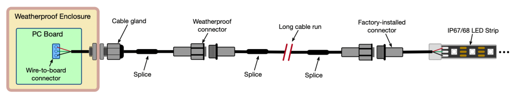
Many weatherproof (IP67/68) LED strips come with a pre-installed weatherproof connector, and it’s common to use the same type of connector at both the LED end and the controller end of the long cable run. This makes it easy to install and replace components or the cable itself. Although these connectors are very inexpensive, widely available from Amazon and other sources, and appear to perform well (based on limited data), there are a couple of downsides:
- Most inexpensive weatherproof connectors cannot be user-assembled; that is, there are no provisions for the user to directly attach or solder wires to the connector body itself. Instead, a short “pigtail” cable, typically ~20cm (8″), is factory-installed on each side of the connector assembly. It’s necessary to splice additional lengths of cable to the pigtails, as shown in the diagram above. With at least three splices per LED strip connection, the splice fabrication time becomes signficant.
- In some cases the factory-installed connector may be undersized for your application. In the case of the IP68 WS2815 strips from BTF-Lighting that I’ve been using lately, the connector is rated at 2A and is fabricated using 24 AWG wire in the pigtail that attaches to the LED strip. At full brightness, a full 5m 300-LED strip consumes about 3.6A, and the connector pigtail becomes noticeably warm after 30 minutes or so.
Both of these problems can be solved by using a different type of connector, but this may require cutting open the LED strip’s silicone sleeve, soldering different wires, and then restoring the sleeve. See the LED Strips section for instructions on how to do this.
If reliability is of greater importance than ease of assembly/disassembly, there is another option that greatly reduces the number of connectors and splices in the system. This approach is illustrated below.

With this approach, the long cable is soldered directly to the LED strip. If the LED strip needs to be replaced, the cable is replaced along with it (and can be detached and reused “back at the shop”). The key to this approach is selecting a wire-to-board connector that allows the cable to be threaded through the cable gland for installation and replacement. But the opening in the cable gland is very small, barely larger than the cable diameter. “What be this kind of magic”, you say?
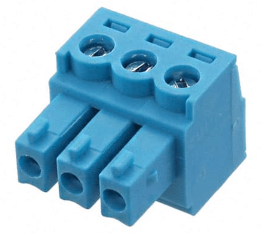
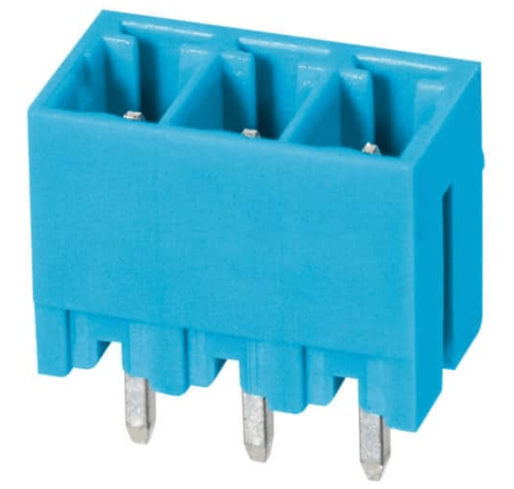
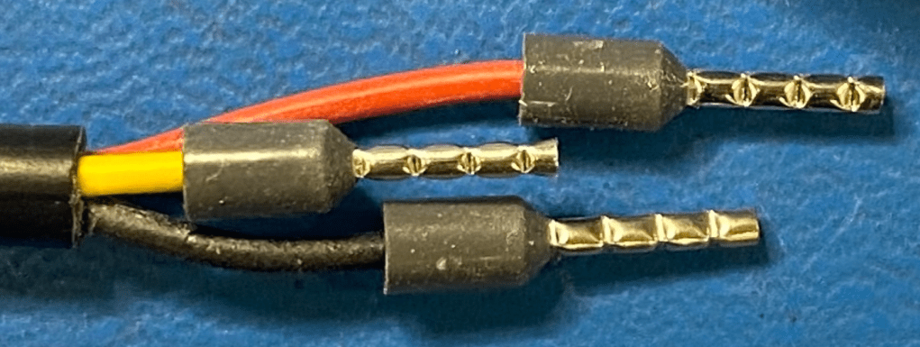
My solution is to use pluggable terminal blocks for the internal wire-to-board connections. These have two parts: a header that is soldered to the PC board, and a plug that contains the screw terminals. The ability to separate the header and plug makes it much easier to screw in the wires after passing the cable through the gland. Although the screw terminals will accept bare wires, I prefer to use wire ferrules for increased reliability and security of the connection. In some cases it’s necessary to “stagger” the wire lengths to allow the ferrules to all be passed through the gland, as shown below.
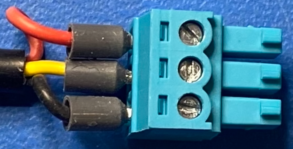
The particular terminal blocks that I use (header, plug) are rated at 8A, ample for most LED connections. There is another slightly larger series rated at 20A (header, plug) that I use for power supply connections.
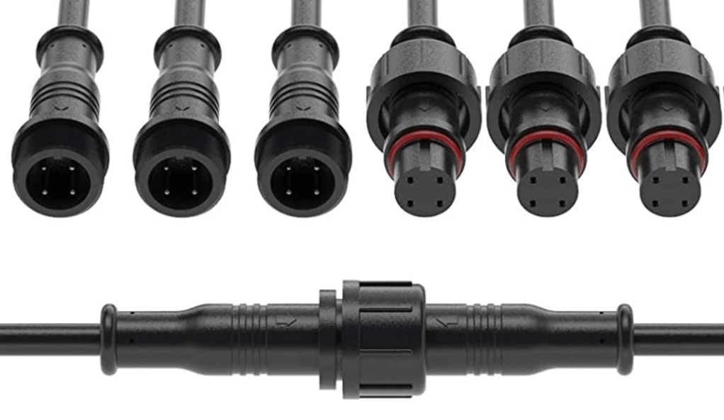
If you choose to use external, weatherproof connectors in your cable runs, there is a wide array of choices available. I hesitate to make specific recommendations without direct experience, but here are some suggestions:
- Depending on the criticality of your application, give preference to connectors that can be procured from reputable electronics distributors (Digikey, Mouser, etc.) that provide detailed data sheets. These connectors are likely to be much more expensive (probably for valid reasons) than what can be found on Amazon or AliExpress. Note that I sometimes don’t follow this advice if I’m feeling lucky.
- To further improve the reliability and lifetime of weatherproof connectors, apply liberal amounts of dielectric (silicone) grease to the contacts before mating. This provides an additional layer of protection against moisture, and also acts as a lubricant.
Cable Glands
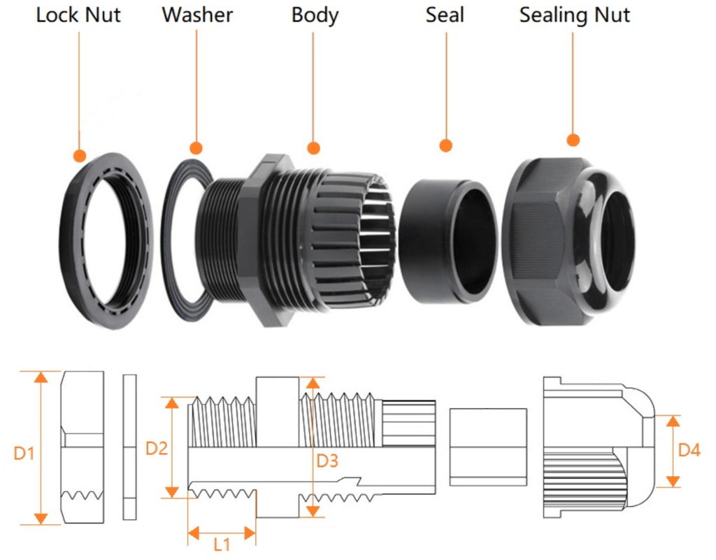
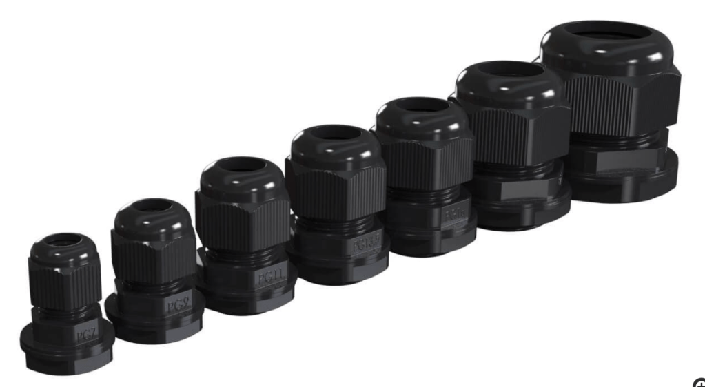
A cable gland (also known as a cord grip or cable strain relief) serves two functions. Primarily, it provides a weatherproof path to pass a cable through an enclosure wall. It also provides mechanical support to the cable, preventing externally-applied forces from being transmitted through to the components inside the enclosure. They come in a wide range of sizes to accommodate different cable diameters.
Each size of cable glad is designed to achieve its IP rating (often IP68) with a specific range of cable diameters, assuming that the cable has a round cross-section. Some cables have a flattened-oval cross-section, and this can be somewhat mitigated by adding a short segment of marine-grade heat shrink tubing at the point where the gland grips the cable.
When selecting a cable gland, pay special attention to the length of the threads that will pass through the enclosure wall (dimension L1 in the diagram above). In the smaller sizes, this dimension is often 8mm. This may not be enough to accommodate the thickness of the wall while also allowing the nut to engage with an adequate number of threads. The consequence (learned from personal experience) is that a tug on the cable may result in the entire gland popping off of the enclosure. A quick search shows that glands with longer threads are available, but are rare.
One other cautionary note: whenever possible, mount glands in locations on the enclosure where the cable seals will be protected from direct rainfall or indirect dripping water. The cable itself can provide a path for water droplets, so it’s advisable to add a “drip loop” to any cable just before it reaches the enclosure.
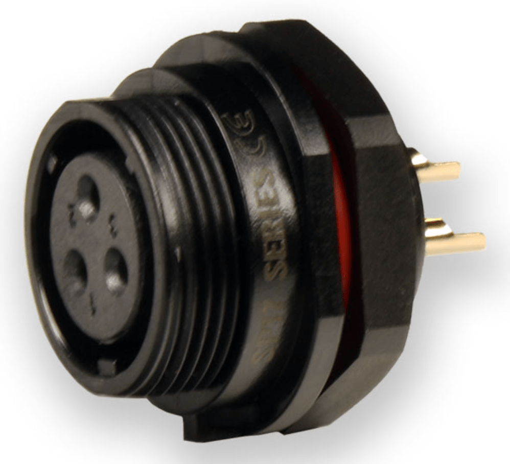
Note that there’s an alternative to using cable glands. A panel-mounted weatherproof connector that allows a cable to be directly plugged into an enclosure. This still requires a short cable between the panel-mounted connector and a wire-to-board connector inside the enclosure. A possible downside of this approach is that connector families that include a panel-mount variant tend to be more expensive.
Here’s a photo of an LED controller that uses all of the techniques described so far in this article.

Controller Circuit Boards
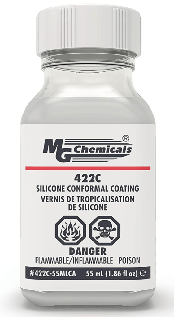
Assuming that your controller electronics are installed in non-ventilated weatherproof enclosures, all of the cable entry points are sealed with good-quality cable glands, and maybe you’ve added a desiccant packet to soak up any wayward moisture, you should be in good shape. But there’s one additional level of protection that can be added: conformal coating. This is a thin layer of non-conductive, waterproof material that can be applied by brushing, spraying or dipping. Various coating materials are available, but silicone-based conformal coating appears to be the most common for DIY projects. It’s easy to apply (I use the brush-on type) and dries quickly. For me, the jury is still out on whether conformal coating is really needed. Perhaps it makes the most sense in very humid climates.
LED Strips
In Manta Ray (Fly By) Update #1, I described my rationale for selecting IP68-rated LED strips (not IP65 or IP67) for long-term outdoor installations. In my Desert Shark article I described a technique for cutting and attaching a cable to an IP68 LED strip. Although this focused on a 2-wire non-addressable LED strip, the same technique applies to 3- and 4-wire addressable strips.
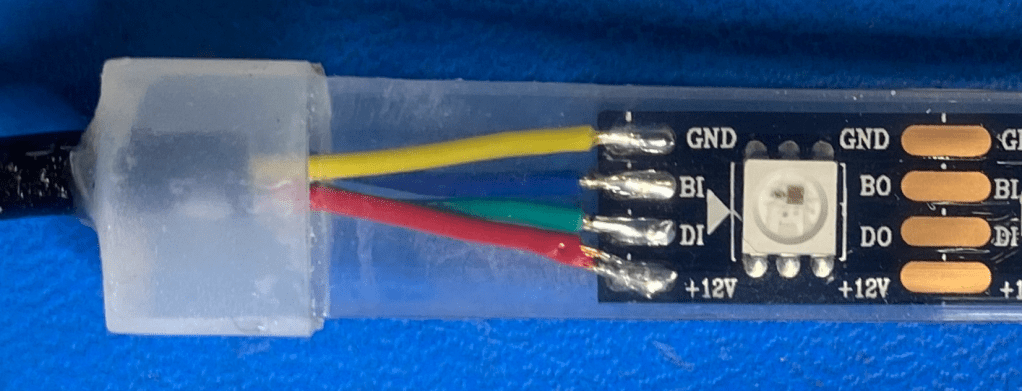
Since I wrote those articles, I’ve slightly refined my technique to achieve a more robust connection. The factory-installed connection on my IP68 WS2815 strips look like the photo at right. The end of the cable jacket is captured inside the silicone sleeve, both protecting it from water intrusion and providing strain relief. This is facilitated by the extra length of sleeving at the end, which is not available when the strip is cut and the typical end caps are used.
When an end cap is used on a cut strip, the cable jacket ends up outside the end cap. On the Desert Shark, I added a piece of 1/4″ heat shrink tubing that covered the cable jacket end and butted up against the LED strip end cap. But that had a bad side effect – it created a bending stress point where the unjacketed wires enter the end cap. Now I’ve addressed that by adding a piece of 1/2″ heat shrink that completely covers the end cap and overlaps the narrower heat shrink, providing a good mechanical connection between the strip and the jacketed part of the cable. In this application it’s important to use marine-grade (adhesive) heat shrink tubing with a 3:1. shrink ratio, meaning that it will shrink to 33% of its original diameter. The only downside is that the heat shrink covers up the first LED in the strip.


Maintenance
Any long-term LED lighting installation is going to need periodic maintenance, with the frequency depending a lot on the environmental conditions. This will be much less painful if the lighting system was designed to allow all the components to be easily inspected and replaced if necessary. That’s one reason why it’s very important for the lighting designer to begin collaborating with the sculpture/installation artist as early as possible. Even so, it won’t be easy, since accessibility is usually at odds with aesthetics.
Here are some typical tasks for a maintenance visit:
- Brush, blow, or vacuum dust and dirt from the LED strips, other light fixtures, and the electronic enclosures.
- Inspect for cracked enclosures, connectors and cable jackets.
- Replace desiccant packets.
- Inspect (on a sample basis) external connector contacts for any sign of water intrusion or corrosion. Add dielectric grease as necessary.
OK, then…
Hopefully this article will be helpful to you on your next project. There are many related topics that I didn’t cover, so please let me know if there’s something specific you’d like me to add. I’ll provide updates based on new discoveries and experience. Thanks for reading!

Awesome! Thanks.
for Science, -Alex Krause
>
LikeLike
Great article Keith.
LikeLike
Very thorough and great experience. Thanks for writing these posts
LikeLike
You’re welcome! Thanks for the feedback
LikeLike