Happy New Year!
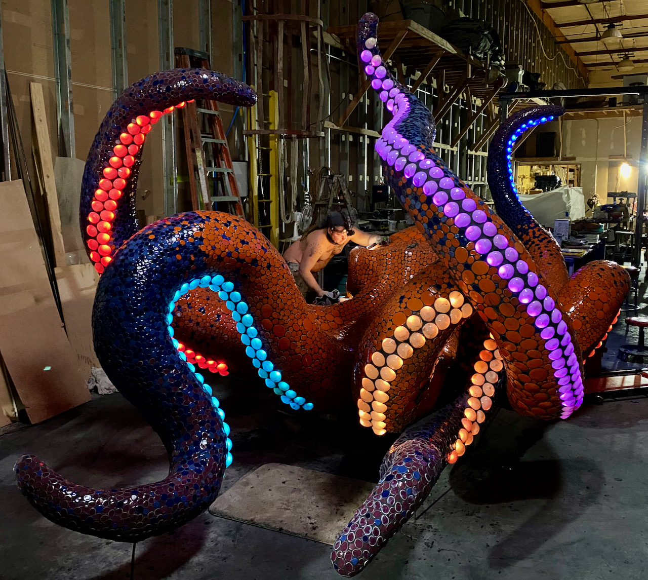
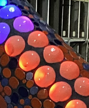
Last month I described the early progress in building a 22-foot ceramic tile octopus sculpture that is destined for a commercial building complex in Morro Bay, California. The sculpture itself is now 95% complete, and all 405 of the WS2811 pixels have been mounted underneath the translucent glass “suckers”. The pixels and suckers were affixed with hot-melt adhesive, and then the suckers were further captured by a surrounding layer of tile grout.

Only six of the tentacles have lights; the other two are very low to the ground. Each of the six strings of WS2811 pixels is driven by one of the outputs from the FLiCR controller board described in last month’s post.
One of the new challenges on this project was in how to weatherproof and otherwise protect the controller and power supply. Unlike most of my previous projects, the artist made no provisions to mount the electronics inside the sculpture. Since this is a permanent installation in a public setting, the electronics will be exposed to sun, rain, fog, and climbing people. The latter factor led me to decide on a metal enclosure rather than the plastics ones I’ve been using lately, as described in my article on weatherproofing.
I was also very concerned about safety factors related to the 110 VAC input to the power supply. I don’t yet know this for certain, but I’m fairly sure that the installation will be subjected to a municipal building code (i.e. electrical) inspection and approval. This means that all high-voltage wiring/connections need to be inside the metal enclosure or code-approved wiring conduit (metallic or PVC), and that all metal surfaces need to be grounded. These requirements led me to conclude that it would be much easier to mount the power supply inside the enclosure along with the controller board.
To avoid excessive heat inside the enclosure, I selected the Mean Well HLG-240H-12 power supply. This type of power supply has a good thermal conduction path between the internal electronics and the aluminum case, so it’s bolted firmly to the back of the enclosure, with a layer of non-silicone thermal grease to improve thermal conductivity. The power supply is attached to the enclosure with stainless steel screws and bonded neoprene sealing washers.
To keep the enclosure as small as possible I had to mount the power supply at an angle. I know, a little bit cheesy-looking…

The enclosure I selected is pre-painted cast aluminum with an IP66 rating. The aluminum was very easy to drill (compared to steel), but brings an additional consideration. Any mechanical connection between dissimilar metals (like aluminum and galvanized steel) can result in galvanic corrosion, especially in the presence of moisture. That means that any external metallic conduit (typically galvanized steel) cannot directly connect to the enclosure. That led to some interesting decisions.
The 110 VAC service will be provided at the installation site by the customer, and it seems most likely that they will use 3/4″ Intermediate Metal Conduit (IMC), which is rugged and designed for outdoor use. So on the enclosure I provided a 3/4″ PVC terminal adapter fitting with a sealing washer and locknut. In any case, an additional PVC fitting can be used to adapt to whatever type or size of conduit is used, while providing isolation between the aluminum and galvanized steel conduit.

The enclosure will be mounted low on the sculpture’s body, between two tentacles to minimize visibility. The body will be notched out slightly to provide strong support, while allowing the conduit to exit the bottom of the box without obstruction. There are six 18 AWG 3-conductor cables for the tentacle LEDs, plus one more for the string of ten WS2811 LEDs that backlight the translucent glass eyes. These cables exit the body from a crevice that’s about 4 feet (1.2m) from the location of the box. Since these cables need protection from rain, sunlight and physical damage, I chose 3/4″ “liquid-tight” PVC flexible conduit, which attaches to the two fittings shown in the lower left of the enclosure photo (above).
One other interesting (?) point about the enclosure: I added a waterproof breathable vent at the bottom. Although this vent allows warm air to escape and reduces the internal temperature rise to some degree, the main benefit is in maintaining pressure equilibrium between the box interior and the ambient environment. This reduces the possibility that any moist/humid air trapped within the enclosure will condense into water under environmental temperature and barometric pressure changes.

Many of my projects have an AC power source that is manually turned on at night (like a generator) or is on an automatic timer. In this case, the lighting controller needs to enable the lighting at dusk and then turn everything off at dawn. One option to implement this is with the battery-backed time-of-day clock provided by the FLiCR controller board. But this approach has some complexities, like dealing with daylight savings time and seasonal changes in the duration of “nighttime” hours. Instead, I chose to use a simple ambient light sensor that is mounted to the bottom of the enclosure, aligned with a small hole that allows ambient light to enter. A small piece of clear Plexiglas provides a watertight seal behind the hole.
The ambient light sensor is just a photo-transistor that produces a voltage (0 – 3.3V) that is proportional to the intensity of light that hits its face. This signal is read by one of the analog GPIO inputs on the Teensy 4 microcontroller, which determines whether the ambient light level is below a settable threshold. If so, a pre-defined FireScript* sequence is triggered, and continues to run until the ambient light level goes above the threshold. To prevent false triggering, I implemented some semi-fancy filtering and thresholding algorithms. These algorithms deserve their own article, so I’ll save that for later. [* the FireScript scripting language is introduced near the end of this article, although it’s evolved a lot since then. Another article, someday…]
In last month’s update post I described the four lighting effects that I planned for the Octopus: FADE, FLOW, PULSE, and WAVE. These are all now up and running. Below is a video of a quick demo utilizing a combination of the FLOW and WAVE effects.
I’m now working on an additional effect called ZAP, in which a high-power “laser beam” flies down the length of a tentacle, leaving behind a trail of flickering embers that slowly fade away. It was especially challenging to make the flickering embers look realistic. Flickering a single pixel wasn’t that hard, using a random number generator (RNG) and a filtering/smoothing function. But applying the same flicker effect to all pixels looks horrible, since the flickering is synchronized. To address this I defined four different “ember types”. When the ZAP effect starts, each pixel is randomly assigned to be one of the 4 ember types, Then, each ember type is randomly assigned a flicker frequency from a pre-defined range. During execution, the flicker effect for each ember type uses a separate call to the RNG as a further measure to minimize synchronization among nearby pixels. There are additional details that I won’t go into now, but here’s a demo video showing my current progress. I haven’t mastered the process of of capturing LED effects in photos/videos, and this effect looks much better in person.
The customer in Morro Bay won’t be ready to install the Octopus until May 2023, so I’ll probably allow myself to get distracted by other projects before I cross the finish line of the all the effects for this piece.
Thanks for reading!

Looking great Keith! Such a great size sculpture.
Curious if you considered using a 120V light sensor to turn off the power supply (which would turn off everything)? It’s a very different solution though, and a bulkier sensor too.
LikeLike
Hi Marc! Thanks (again) for reading my article carefully and providing feedback. I did briefly consider using an off-the-shelf light sensor on the AC side. It would provide an advantage in power saving, but has a few downsides: 1) Would need to be mounted outside the enclosure and would require some additional conduit-enclosed wiring; 2) If it has the ability to set the switching threshold, the control might be susceptible to tampering; and 3) More expensive. On the sensor I used, I implemented a “signature detection” capability so that I can use a series of pulses from a flashlight to do things like change the script, without having to open up the enclosure and press a button. This is a cheesy, temporary substitute for the Bluetooth or WIFi remote control capability that I’ve been planning for a while.
LikeLike
Yes, that all makes sense.
Ha, manual light pulsed settings! Love it.
LikeLiked by 1 person