As I predicted in last month’s project update, there have been lots of distractions that have prevented me from fully completing the Octopus project. First, the massive amount of snow we’ve had this year in the western United States has motivated several ski trips. Lots of fun both here at Lake Tahoe and in Utah. Second, I’ve taken on a major overhaul of my woodworking shop. I’ve promised myself that I’ll try to find more time this year for woodworking projects, and maybe I’ll write about that…
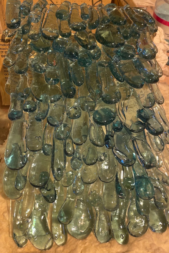
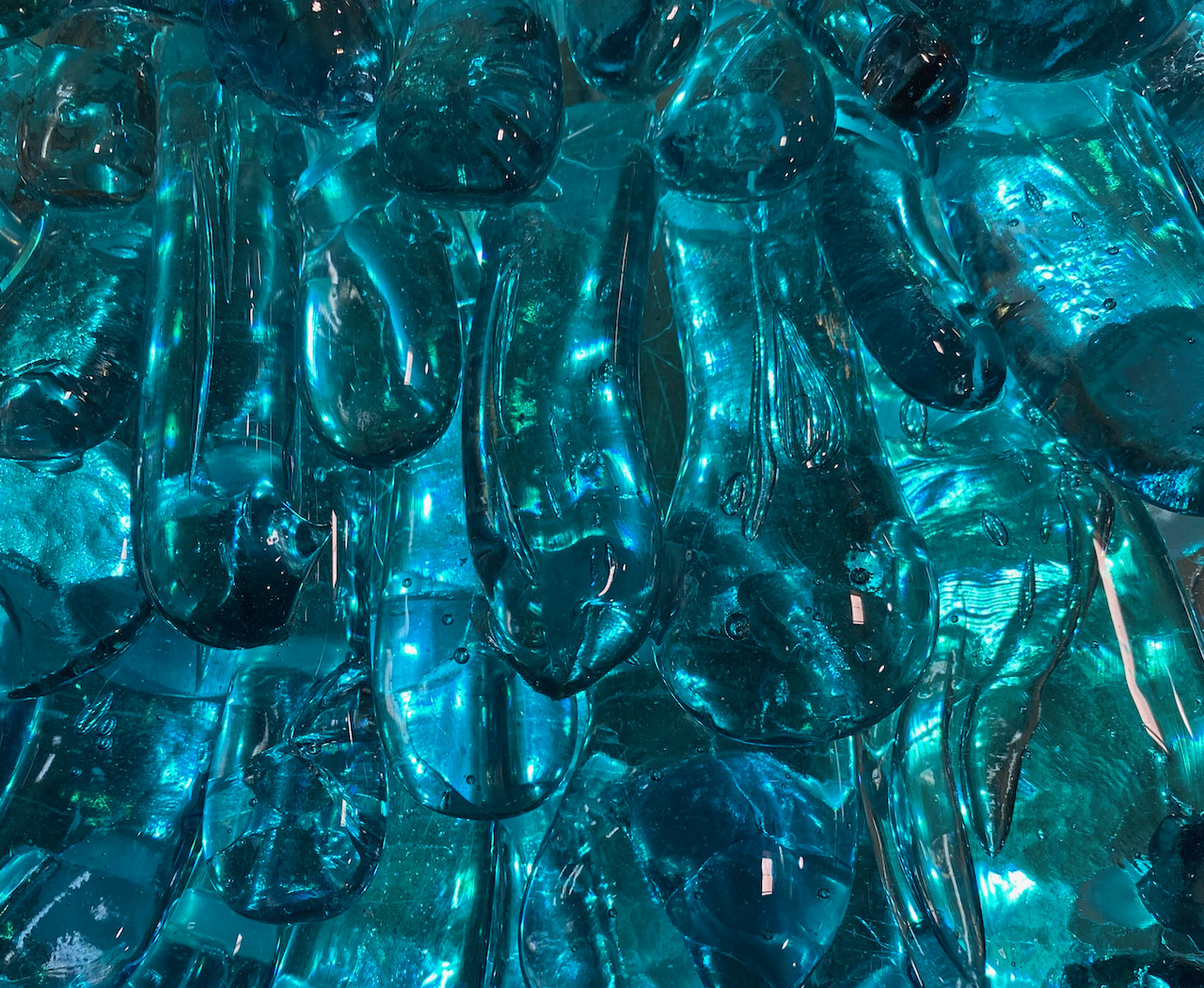
The biggest distraction has been a new project cooked up by my artist friend Peter Hazel. He’s in a competition for a commission from a US city for a large sculpture that celebrates some of their local folklore. I won’t say too much about it, except that it involves a simulated waterfall made with “droplets” of solid glass. The waterfall could be as much as 16 feet (5m) tall. At right is a photo of the small panel he made to test the concept.
He asked me to build a LED panel that could backlight the glass with animated “waterfall” effects. I had no previous experience with 2-dimensional LED panels, so this seemed like a good opportunity to learn something new.
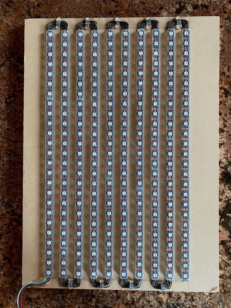
Until I know more about the size of the waterfall in the actual sculpture, and the size of the glass droplets, it’s hard to determine the optimal LED spacing in both the vertical and horizontal axes. So for the LED test panel I decided to use strips with 60 LED/meter density, mounted vertically and spaced 1 inch (25.4mm) apart horizontally. I used sections of IP68 WS2815 (12v) strips that I had left over from the Desert Shark project. For simplicity, I wired these to use a single controller output with the segments in a serpentine arrangement.
For the controller I used the same FLiCr board (based on the Teensy 4.0 MCU) that I used for the shark and several other projects.
My first attempt at the “waterfall” animation was based on a moving sine wave effect. I’ve used this effect successfully on the Octopus and other projects, and it looks pretty good with a single strip/string of LEDs. But I made the mistake of applying the same sine wave synchronously to all 10 LED columns. The result looked like the moving light bar on a document scanner — not like water at all. A reasonable next step would have been to apply randomly-selected wavelengths and travel speeds to each column, but that didn’t occur to me until just now (ah, hindsight!). So maybe I’ll go back and try that, but what I did instead was to create an entirely new (to me) effect based on an a C++ class I called droplet. Each droplet that flows down a waterfall column has a max-brightness head and a trailing tail that linearly decreases in brightness. The head also has a short, leading ramp that improves the smoothness of the effect.

The characteristics of each droplet are controlled by the following parameters:

When initiated (or “launched” as I say), each droplet starts with the the leading-edge ramp at the top of the waterfall, which is defined as position = 0mm. The droplet flows down the column, at a speed dictated by the initVelocity and acceleration parameters, until the end of the tail reaches position = columnLength. That triggers a new droplet. Upon launch of a droplet in a column, the length of the tail (tailLength) is randomly selected within a range defined by the minTailLength and maxTailLength parameters. So even though the speed and acceleration of all droplets are the same, the variable tail length affects the amount of time required for a droplet to reach the end of the column. That results in a high degree of randomness in the positions of the droplets across the waterfall columns.
Both the animation of the droplets and the updates of the individual pixels in the LED array are based on a fixed frame rate, which for most of my projects is 100Hz (10ms period). For each frame, the position of the droplet in each column is updated as described above. Then for each pixel in a column, a new brightness value is computed based on the position of the pixel relative to the current position of the droplet in that column.
Let’s use pixelNum = 7 as an example, as illustrated in the diagram above. First, the position of the pixel (in mm) is computed as pixelPos = pixelNum * pixelSpacing. For 60 LED/m strips, pixelSpacing = 16.67mm. Then the pixel position is compared to the leading and trailing edges of the droplet to see if there is any overlap. If not, the brightness value of that pixel is set to 0. But if ((pixelPos < dropletHeadPos) && (pixelPos > (dropletHeadPos – headRampLength – headLength – tailLength)) the pixel falls within the boundaries of the droplet. Then the position of the pixel relative to a specific portion of the droplet is computed in order to determine the brightness. In the example, pixel 7 falls within the tail, at 75% of tailLength relative to the end of the tail. So the brightness value of pixel 7 is 0.75.
Well, it’s a little more complicated than that. The “baseline” color of each waterfall pixel is influenced by the variable baseColor, which is defined in the HSI color space. HSI is similar to the HSV color space. See this article for more information on my use of HSI colors. An HSI color has three components (hue, saturation, intensity) and the value of each component ranges from 0.0 to 1.0. For each frame, other animation effects are also applied to the pixels, and these effects can modify any or all of the baseColor components. For example, the fade effect produces a smooth transition from the current baseColor to a new color (all HSI components) over a specified duration. The droplet effect, which modifies only the intensity (.i) component of the pixel color, is applied after all of the other effects have been applied during each frame. The computed value of the droplet effect (for a specific frame and pixel) doesn’t actually set the pixel intensity, it just scales the intensity based on the underlying baseColor. For each pixel k,
pixelColork.i = baseColork.i * dropletValuek
This approach allows multiple effects to be combined, so that the intensity-modulation droplet effect can continue running while the overall hue/saturation of the waterfall is being changed. Note that this approach is very much facilitated by the fact that the HSI components and the effects that influence them all are constrained to the range 0 – 1.
Well…one more thing about pixel intensity. To compensate for non-linearities in the perception of different “brightness” levels by the human eye, a technique called gamma correction is applied when converting HSI colors to the RGB color space used by most LED strips. See this article for a more detailed description of gamma correction.
OK, blah, blah, blah, but what does the droplet effect look like? Here are a couple of short video, but please take my word that these looks much better in person. I definitely haven’t mastered the art of making LED videos. The first one was taken with the LED panel behind a frosted acrylic diffuser:
And this one is with the LED array behind the waterfall test panel, without any diffuser. Note that the overall color smoothly fades from blue to aqua.
My current implementation supports only a single droplet on each column. This looks fine on the very small test panel, but won’t scale well to a huge waterfall. So my next step is to extend the implementation to support a configurable number of droplets on each column, with a randomized spacing between adjacent droplets. And I’ll probably circle back and test a randomized sine wave effect, but I suspect that this won’t look as good.
It will likely be a few weeks before we find out if Peter gets the commission to build the waterfall sculpture. Even if he doesn’t, I think the droplet effect (or variations thereof) will be useful for other projects in the future. And I’ve got a very cool idea that I’ll save for a future article.
Thanks for reading, and let me know what you think!
P.S. Check out the Index page for additional articles that you may find interesting.

That looks very promising Keith! Though as you say, scaling to a much larger size will be the challenge/fun. 🙂
Hmm, maybe you plus in a little of your random sin wave effect too.
Perhaps check out 2d Blur as well. https://youtu.be/bsGBT-50cts
-marc
LikeLike
Nice clean build!
LikeLike