Now seems like a good time to write about the LED controller that I’ve been using for the last year or so. I based the Olympic Rings project on this controller, but there are several prior and subsequent project that I haven’t posted about yet (stay tuned for those). I originally designed the OpenRocket board for an art piece for Burning Man 2020, which ended up being cancelled due to Covid. The context of this effort was the Black Rock Forest Project, which aimed to inspire artists from around the world to create “trees” that would populate a section of the Black Rock Desert during the Burn. The overall project didn’t gain much momentum before the event cancellation, but I got pretty far along on my tree, which I called RockeTree (Rocket + Tree). My goal was to provide the controller board (and the hardware design and source code) to other artists on an open-source basis. Hence the name OpenRocket.
OpenRocket Hardware Features
The board design incorporates a powerful PJRC Teensy 4.0 microcontroller unit (MCU) and provides the following features:
- Five level-shifted outputs to drive addressable LED strips
- Four general-purpose PWM MOSFET outputs to drive non-addressable LED strips, motors, solenoids, etc.
- Two debounced, general-purpose switch inputs to trigger sequences, set modes, etc.
- An input for a PIR motion sensor for sequence triggering
- A differential I2C interface to support remotely-located sensors, including an ambient light sensor.
- A differential RS-485 interface to support communication with other lighting controllers.
- A battery-backed real-time clock (RTC)
- A microSD cards reader to store light sequence scripts and color palettes
Microcontroller Unit (MCU)
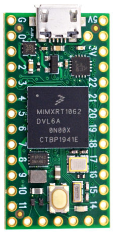
Although there are many Arduino-compatible microcontrollers to choose from, the Teensy 4.0 MCU (T4) seems ideal for my projects. It’s extremely fast: the 32-bit ARM Cortex-M7 processor runs as 600 MHz, and incorporates a 32/64-bit floating point math unit. That means that I can design my lighting effects to use complex math functions that model real-world physics and geometry (i.e. trigonometry) without having to settle for a slower frame rate. The T4 also has tons of memory: almost 2MB of Flash, 1MB or RAM, and 1KB of EEPROM (emulated using Flash).
Another important feature is the large number of GPIO pins, including 31 pins that support PWM with up to 15 bits of resolution.
All that for only $20 USD. PJRC also makes a Teensy 4.1 for $27 USD, but it is physically larger and includes many additional features that are not useful to me. The one exception is the Micro SD card socket on the T4.1. But I’ve found that it is more cost effective for me to stick with the T4 and add the Micro SD capability on the OpenRocket board (see below).
The T4.0/4.1 boards do not provide any on-board wireless connectivity (e.g. WiFi or Bluetooth). The ESP32 MCU is heavily used in the LED lighting community particularly because it does provide well-integrated wireless options. However, most of my projects do not require or particularly benefit from WiFi connectivity, due to the external infrastructure required (e.g. WiFi router, internet access). A peer-to-peer Bluetooth interface, on the other hand, could be very useful useful. See more on this in the User Interface section below.
Power Supplies
I decided long ago to settle on 12V as my “standard” power supply voltage. When a project requires LED strips, I typically use addressable WS2815 strips or non-addressable 5050 strips, both of which use a 12V supply. Since LED brightness is a function of power (voltage x current), a desired brightness level can be achieved by a 12V LED strip that uses only 42% of the current required by a 5V strip with the same brightness. Since voltage drop (“droop”) that occurs in long LED strip runs is a function of the square of the current (Vdrop = I2 x Rwire), the reduced current needed by 12V strips is a huge advantage. Longer runs can be achieved without seeing color shifts caused by voltage droop, the need for “power injection” is reduced, and generally smaller-gauge wire can be used.
The T4 MCU accepts a 5V power supply input, and incorporates a regulator to produce the 3.3V supply needed by the processor chip and other parts. This 3.3V supply is also connected to a board output pin, although the pin is specified to supply a maximum of 250mA off-board.

The components on the OpenRocket board require three different voltages: 12V, 5V and 3.3V. The 12V level is provided by an external 12V power supply unit with a current rating appropriate for the specific project. The OpenRocket board implements a high-efficiency switching regulator circuit that converts to the 12V input to the 5V supply used by several of the OpenRocket board components. Some other components require 3.3V, and this is provided from the 3.3V output pin on the T4.

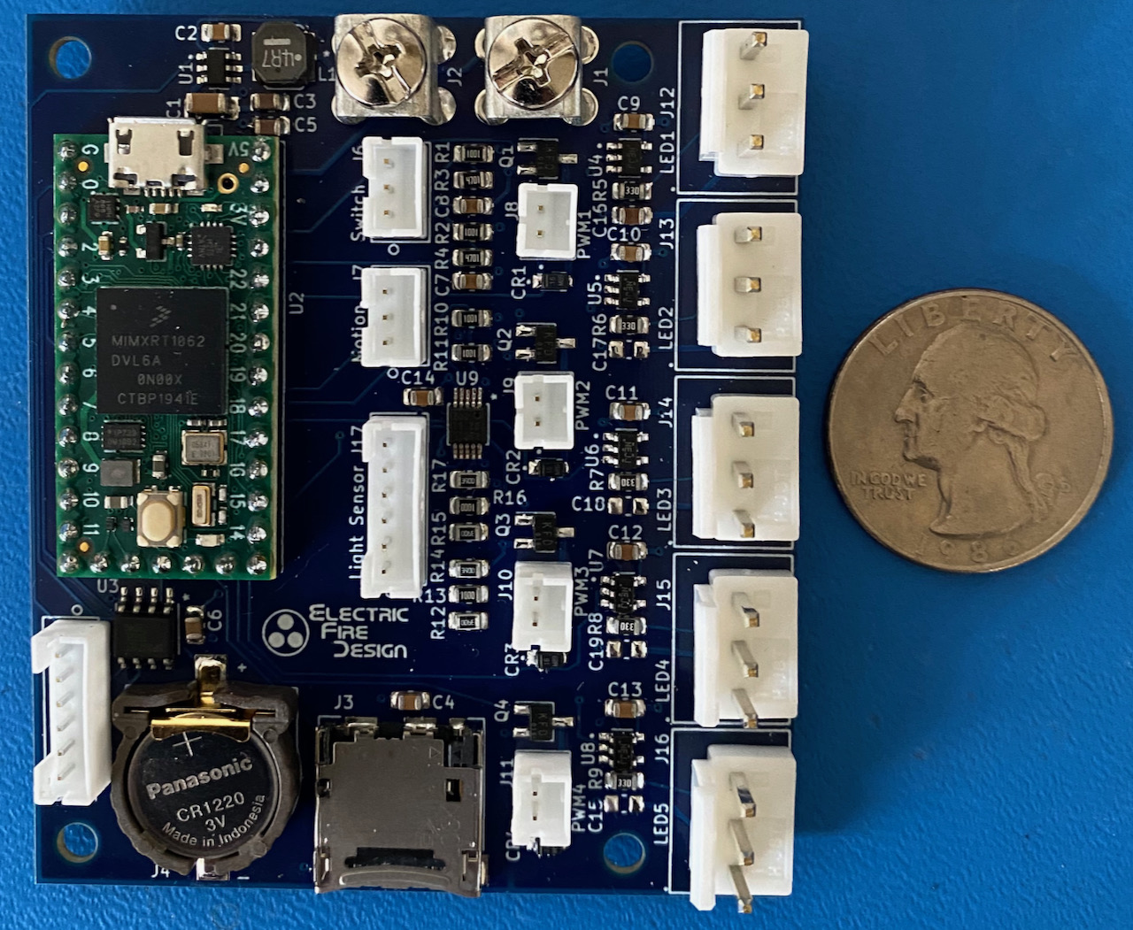
12V power is routed from the power supply input to the addressable LED and PWM output outputs (see those sections below), and the total current drawn from the power supply and routed to the various connectors can be as high as 12 Amps. Due to this high current requirement, I used individual screw terminal, rated for 15A, for the connections between the board and the external power supply.
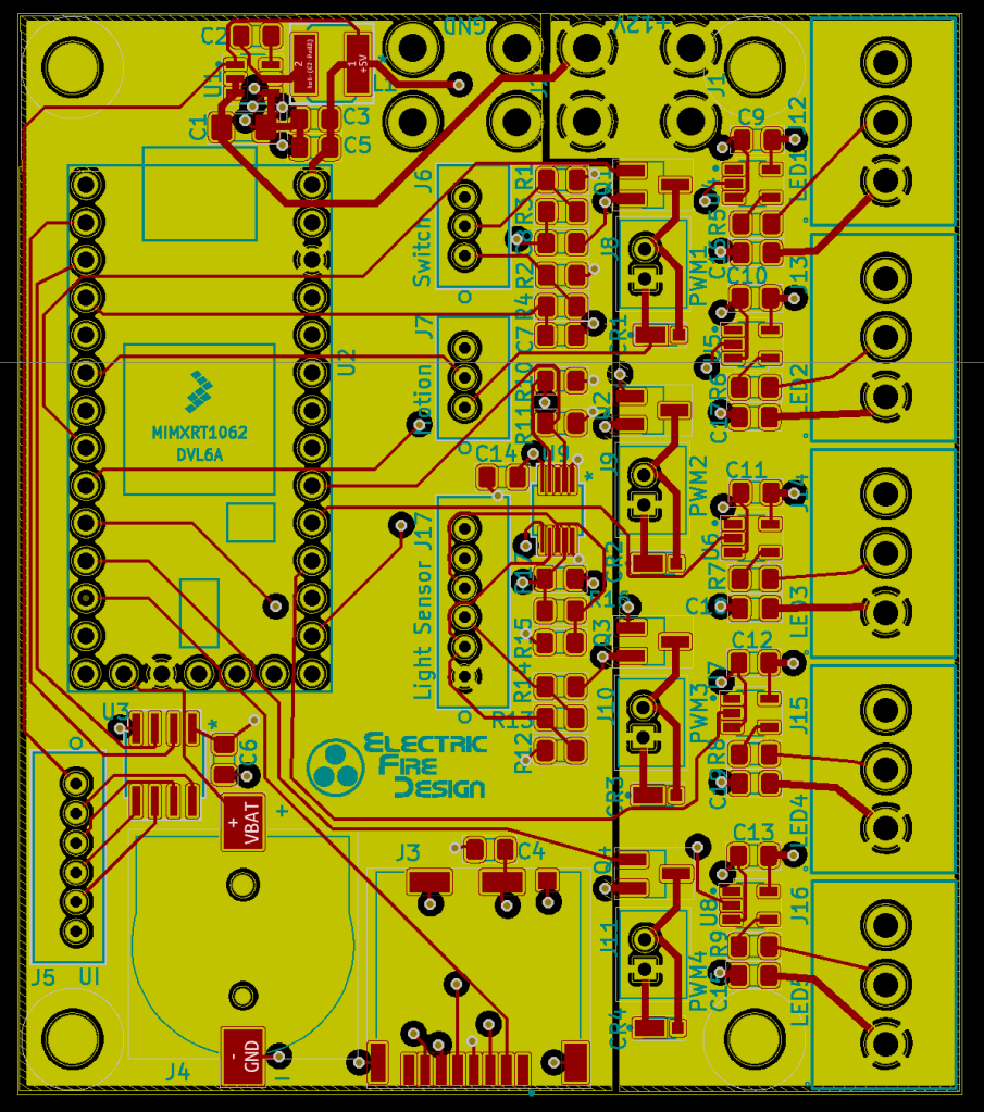
The OpenRocket printed circuit board (PCB) is implemented using four copper layers. The top and bottom layers are used for signal traces, and all components are mounted on the top side. One of the middle layers is a ground plane, providing a low-resistance current return path from various components/connectors back to the Ground screw terminal. The other middle layer is a split power plane. All of the components/connectors utilizing the 12V supply are on the right side of the board, with a 12V power plane directly underneath and providing a good path from the 12V screw terminal. The larger left part of this layer is used for a 3.3V power plane.
Although the regulator circuit shown above has worked perfectly, the global chip shortage has severely constrained the availability of chips like the one I used here. I’m now down to my last one, and I’ll either have to wait a whole year to get more, or I’ll have to redesign the board using a chip that I can actually buy (spoiler: there will soon be an OpenRocket v2).
MicroSD Card Reader
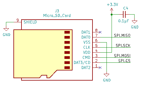
It was surprisingly easy to incorporate a MicroSD card reader into the OpenRocket design. It just uses the four SPI signals (MOSI, MISO, SCK, CS) directly from the T4, with no additional components other than a decoupling capacitor.
There are several different types of MicroSD card sockets. I chose one that uses a hinged card-latching mechanism, thinking that it would be a good compromise between the bare-bones push-in/pull-out type and the more expensive push-in/push-eject type. It turns out that the hinge is a bit fragile and fussy, so for the next revision I’ll splurge on the fancy ones.
The purpose of the MicroSD card reader is to provide an “easy” means for a non-technical person (i.e. a client) to modify the lighting sequences for an art piece without having to modify C++ code, compile it, and download it to the T4 MCU. See the FireScript Scripting Language section below for more details.
Real-Time Clock (RTC)
The T4 MCU incorporates a real-time clock (RTC) to track the time and date, which can be accessed using the Time library. The OpenRocket board includes a socketed CR2032 coin battery so that timekeeping is maintained even when the board power is turned off.
I had planned to to use the RTC as a method for triggering lighting sequences at specific times of the day, or perhaps to select different sequences based on seasons or holidays. But so far I haven’t had a strong reason to use this capability, and I might eliminate the battery in the next revision to free up the board space.
Switch Inputs
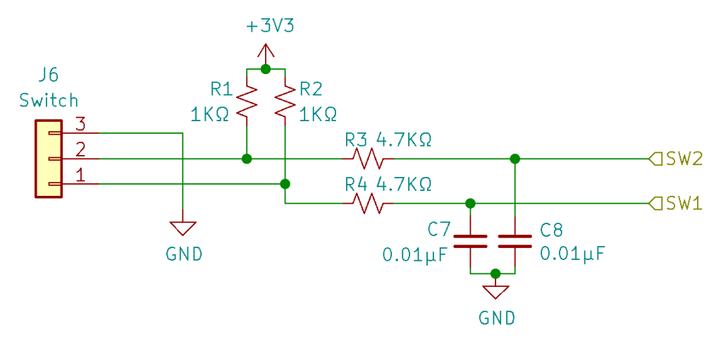

The OpenRocket board supports two general-purpose switch inputs, both available on a single 3-pin JST-PH connector. The RC filter circuits shown at right provide debouncing on both the falling and rising edges of the active-low switch input signals (SW1 and SW2) that connect to T4 GPIO pins.
My experience is that hardware debouncing alone is insufficient to prevent the MCU firmware from detecting multiple signal transitions for a single press of a momentary-action switch. See the Private OpenRocket Libraries section below for information on the software debouncing techniques that I also employ. .
PIR Motion Sensor Input

Some of my projects have required a passive infrared (PIR) sensor to trigger a lighting sequence when a person approaches. PIR sensors like the one shown at right are inexpensive and widely available, although they can be a bit finicky. This one operates over a wide voltage range (4.5 – 20V), and I used 12V. Conveniently, the active-high sensor output is compatible with 3.3V logic levels; otherwise I would have needed a level shifter to avoid damaging the T4 MCU input.
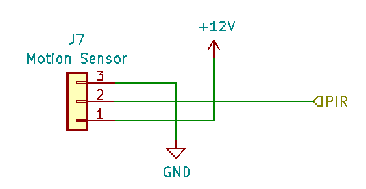
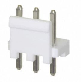
As with the switch inputs, I used a 3-pin JST-PH connector for the three signals to the sensor.
One of the downside of this sensor is that it requires about 60 seconds after each power-up to “calibrate” itself. During that time there should be no motion in the sensor’s field of view (~100º cone angle).
Addressable LED Outputs
The OpenRocket board provides five outputs to drive addressable LED strips that are compatible with the WS28xx serial data protocol. Each output is available on a 3-pin latching JST-VH connector rated for 10A. Each connector provides 12V and Ground to power the LED strip, with a 22µF capacitor on the 12V line to mitigate voltage dropout under transient load conditions. This capacitor is on the small side, but since I used a ceramic SMD part I suspect the performance is actually better than if I’d used a larger through-hole electrolytic capacitor (with higher ESR).
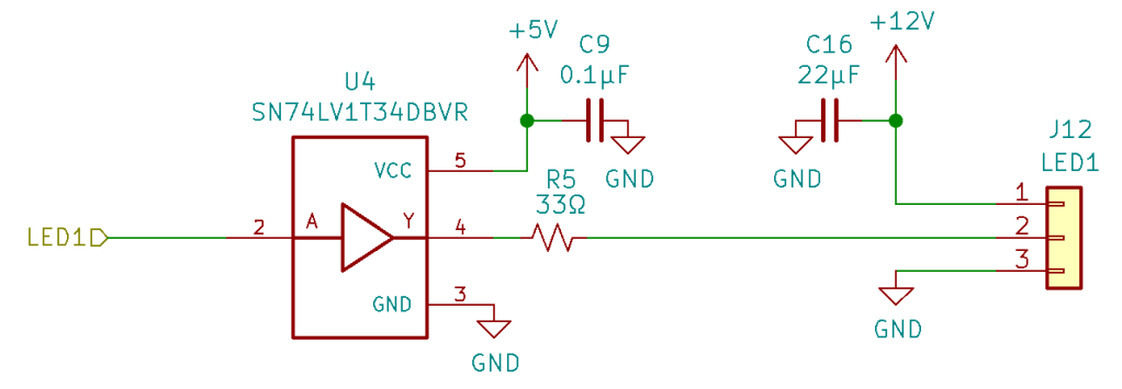
Since the T4 outputs are at 3.3V logic levels and the WS28xx LED data signal requires a 5V logic level, each output has its own level shifter circuit. The single-channel SN74LV1T34DBVR device is in a small TSOT-23-5 package that makes board layout easier, but it is no longer readily available. For the next revision I’ll likely use the ubiquitous 8-channel 74HCT245.
The 33Ω series resistor on the data signal is intended to attenuate noise spikes that may reflect back from the end of the cable attached to the LED strip. This effect is referred to as “ringing”, and without the resistor it could impair the ability of the LED strip (the first LED module on the strip actually) from correctly interpreting the data signal. In theory, the value of the resistor should be chosen based on the characteristics and length of the cable, but a 33Ω resistor has worked fine for all of my projects so far. Other sources state that this series resistor provides some sort of “protection” for the MCU or LED strip, but I’ve found no solid evidence to back up this claim.
Although my go-to LED strip is the 12V WS2815, for some projects, like the Olympic Rings, it’s necessary to use 5V WS2812b LEDs. In this case, the LED power connections are made directly to an external 5V power supply, with only the data signal connecting to the OpenRocket LED connector.
Other types of “clockless” LED strips could be driven by the OpenRocket hardware, but my use of the OctoWS2811 library currently limits me to WS28xx-compatible strips. See the Addressable LED Driver Library section for more details.
PWM Outputs
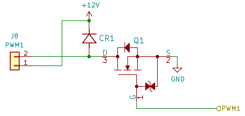
The OpenRocket board provides four general-purpose PWM (pulse-width modulation) outputs in which up to 2A of current can be sinked by an N-channel MOSFET for each output. Each output is accessed via a 2-pin JST-PH connector rated for 2A continuous current. The connector provides access to the 12V power supply, but any voltage up to 30V could be used, based on the rating of the MOSFET. A snubber/flyback diode is included in the circuit to protect the MOSFET when the output is used to drive an inductive load like a motor or relay.
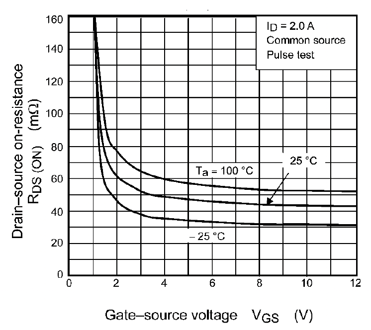
The MOSFET that I chose (SSM3K324R,LF) is considered a “logic-level MOSFET”, since the gate-source voltage (VGS) needed to fully turn on the device (i.e. achieve a low drain-source resistance RDS(ON)) is within the range of the T4 MCU outputs using 3.3V logic levels. As with several parts on this board, this particular MOSFET is not currently available (sigh), so I’ll have to use a different logic-level MOSFET for the next revision.
One thing missing from the circuit shown above is a series resistor between the T4 PWM output and the MOSFET gate. A 220Ω resistor will be included in the next revision. This resistor serves two purposes. First, it limits the current flowing into the gate when the MOSFET is turned on or off, to avoid exceeding the current source/sink capabilities of the T4 output pins. Second, the resistor attenuates (damps) any ringing that may occur in the PCB trace between the T4 output and the MOSFET (dependent on the PCB layout). The T4 MCU’s digital outputs have a programable output impedance and slew rate, so I’ll experiment with this in the future to find the optimal settings and resistor value.
The T4 PWM outputs also have a programmable resolution (up to 15 bits) and PWM frequency (up to 4.6KHz @15-bit resolution). I’m currently configuring these outputs for 12-bit resolution and 1KHz frequency. This enables smooth brightness fades and a reasonably low level of visual flicker.

My main application for the PWM outputs is to drive non-addressable (“analog”) LED strips, either a single white strip using one PWM output, or a single RGBW strip using all four channels. For one project, I used the PWM outputs to drive small DC electric motors in miniature models of wind generators, for a diorama-type art installation.
Ambient Light Sensor Interface
One of my projects required a sensor to detect the ambient light level, so that the lighting would be enabled at dusk and disabled after dawn. The issue was that the artwork was very large, and the controller would be mounted inside a base that had no direct exposure to the exterior ambient light from the sun. The solution was to mount the sensor board shown here behind a small transparent opening in the artwork base.

The sensor is accessed via an I2C interface, but it’s difficult to ensure reliable I2C data transfers for distances over 1 meter. So I mated it with a differential I2C extender board based on the PCA9615 differential I2C bus buffer chip. This board converts the two single-ended I2C signals (SCL, SDA) to two differential pairs, enabling high-speed operation up to about 30m. The board also provides an RJ-45 connector that enables the use of standard Cat 5/6 ethernet cables for the I2C connection.

On the OpenRocket board, instead of using the off-the-shelf I2C extender board shown above, I used the same PCA9615 chip to provide a compatible differential interface with the remote ambient light sensor assembly, as shown below.
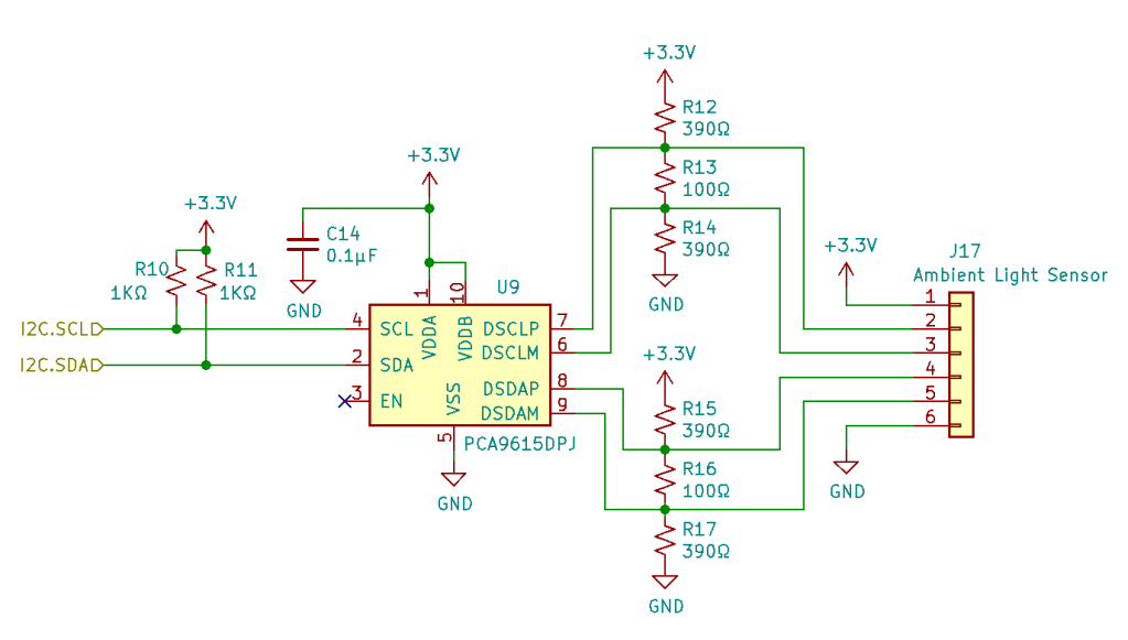
To minimize board space I used a 6-pin JST-PH connector, with a small adapter cable that converts to RJ-45, allowing use of standard ethernet cables for the long run to the remote sensor. The connector also provides 3.3V to power the remote sensor and the differential interface board.
Not to sound like a broken record, but most of the boards/parts described above have limited availability or are no longer available. So while the general idea of using an “extended” I2C bus makes sense for remote-located sensors, I’ll need to redesign this for the next board revision.
User Interface
After my first couple of projects, I realized that I needed an easy way to play around with different colors and other software parameters that affected the appearance and behavior of an art piece. The firmware modify-compile-download process was just too cumbersome and time-consuming. The ideal solution would be an iPhone app that could communicate with my on-board firmware via a Bluetooth interface, which could easily be added to the board design. The existing remote-control apps of this type are very generic and can’t be customized to the degree that I wanted, and I soon realized that I would need to write my own app. Due to the large time investment needed to learn a new language (Swift) and the iOS user interface framework (SwiftUI), I decided to kick this project down the road. Maybe this year.

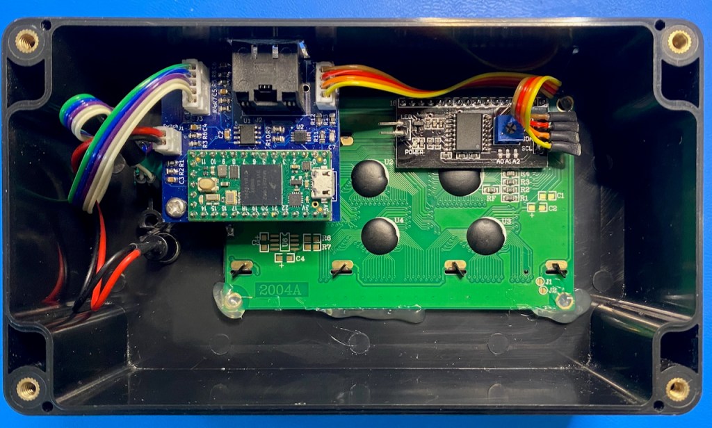
In the short term I decided to make my own user interface device using a hardwired serial interface to the OpenRocket controller. I called this box the Palette, since one of its functions is to aid the process of selecting LED colors.
The Palette contains a custom PCB that hosts another Teensy 4 MCU, and provides the following features:
- 4-row x 20 column liquid crystal display (LCD)
- Rotary encoder with integrated pushbutton switch, used for navigating menus and changing/confirming parameter values
- Additional pushbutton “escape” switch used for menu navigation
- Bidirectional RS-422 serial interface, accessed via an RJ-45 connector
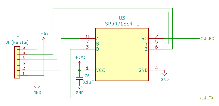
The interface on the OpenRocket side is very simple: just a full-duplex RS-422 transceiver chip. Similar to the light sensor I2C interface, the Palette serial interface uses a 6-pin JST-PH connector, and an off-board adapter enables use of standard ethernet cables for the interconnect. In this case, the connector provides 5V power to the Palette, where the T4 regulates it to 3.3V as needed to power the transceiver chip inside the Palette.
Software Overview
In addition to the board hardware details in the sections above, I’d also like to share some information about the software (firmware, if you prefer) and the important lessons I learned along the way. I’ll try to do that without overwhelming you with too much detail.
The most complex project I’ve completed using the OpenRocket board required about 3600 lines of C and C++ source code, including comments. Of those lines of code, about 64% is organized into eight (private) libraries that I expect to reuse in multiple projects. The remaining 36% is code specific to the particular project. The project-specific code is organized into 16 different files, about an equal number of include files (.h) and C/C++ files (.cpp).
I also used a number of publicly-available Arduino libraries, especially ones that support the more complex hardware interfaces described in the preceding sections. And of course I relied on the Teensy 4.0-specific framework package for the Arduino environment (sometimes referred to as Teensyduino).
Software Development Environment
Like most of you, I developed my first LED project using the Arduino integrated development environment (IDE), an example of which is shown below.
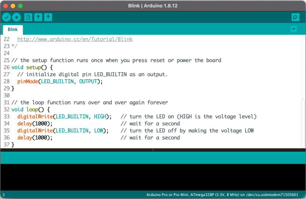
The Arduino IDE was fine when my projects were small and all the code fit into a few files. But as my projects grew more complex, I was encouraged to try a different development environment that uses a combination of Microsoft Visual Studio Code (VS Code) and PlatformIO. VS Code provides a source code editing environment with some incredibly power features. In particular, IntelliSense provides real-time syntax checking, which saves a ton of time by highlighting likely syntax errors as you type without having to invoke the compiler. It also provides smart code completion, meaning that you can type in part of a variable or function name, and the editor will pop up the most likely candidates for you to select. These features alone have dramatically increased my productivity.
VS Code was designed to handle very large, complex projects, and I’m barely scratching the surface of its capabilities. Since it makes switching between files/modules very easy, it has encouraged me to better modularize and organize my code. Here’s what a typical VS Code screen looks like:

PlatformIO is a little harder to describe, but it integrates closely with VS Code to provide an environment and tools to manage your projects. In particular, PlatformIO makes it easy to search for, and incorporate public libraries into your projects, from the over 12,000 libraries available. It supports many different frameworks and operating systems, of which the Arduino framework is just one. And it supports over 1000 different MCU boards. So if you’re currently using the Arduino IDE, it’s about 100% certain that PlatformIO will support your hardware. There are many VS Code and PlatformIO tutorial available on YouTube, including ones (like this one) that explain how to migrate from the Arduino IDE.
Public Libraries
I thought it might be helpful to identify the specific public libraries I used and explain their purpose in the OpenRocket software:
- ElapsedMillis – I use this simple but incredibly useful library whenever I need to create a timing interval of any type (e.g., periodic, one-shot, etc). I described this library and how I typically use it in this blog post.
- SD – This library provides functions to read from and write to a microSD card, but I only use the read functions. It depends on the Arduino SPI library for the hardware interface.
- EEPROM – This library provides read/write access to a small amount of non-volatile memory (1KB in the case of the T4 MCU) that is retained when the board power is removed. I use this memory to store modifiable configuration parameters (like the global LED brightness level) so that the modified values are retained across power cycles.
- OctoWS2811 – This Teensy-specific library is used to simultaneously transfer RGB data to all five OpenRocket addressable LED outputs. It handles all the low-level details and tricky timing of the WS28xx protocol, but imposes minimal load on the MCU processor, since it uses the direct-memory access (DMA) controller that is built in to the processor chip. This allows the software to compute a new “frame” of LED data during the time that the previous frame of data is being transmitted to the LED strips. The net result is a high frame refresh rate even with a large number of LEDs. The only downside is that it requires two RGB data buffers (new frame + previous frame), but this hasn’t been a problem due to the large amount of RAM available on the T4 MCU.
- Sparkfun Ambient Light Sensor – VEML6030 – This library supports the VEML6030 light sensor device used on the Sparkfun board described in the hardware section above. It depends on the Arduino Wire library to utilize the I2C interface.
Private OpenRocket Libraries
So far I’ve implemented eight OpenRocket-specific libraries to implement functions that I expect to be common to many projects using the board.
- SdFileMgr – This library provides a slightly higher-level interface to the public SD library described above. The functions are “tuned” to the specific ways that I utilize the MicroSD card. For example, the readLine() function reads a complete line of text from the currently-open file on the SD card, discarding any line-terminating characters (CR and/or LF).
- Pushbutton – Provides software debouncing and “gesture detection” for the two momentary action pushbuttons that may be attached to the board. The debounce technique uses lockout timing intervals that are generated using the elapsedMillis library, and are described in detail in this blog post (Example 1: Switch Debounce). The library also provides detection of three specific switch gestures: single-tap, double-tap, and long-press. Project-specific code can use these gesture events to trigger different actions, such as: switching to a different lighting sequence script, changing the overall brightness level, or turning the lighting on and off.
- NVM – Similar to SdFileMgr, this library provides higher-level, OpenRocket-specific access to the functions of the underlying EEPROM library. It enables an entire project-specific data structure containing the configuration parameters to be stored and retrieved with a single read() or write() call. It also handles the special case of a first-time board power up, when the EEPROM has not yet been initialized. In this case, a project-specific function is called to initialize the parameters to a set of default values.
- PWM – This library provides for smooth up/down ramps of the PWM duty cycle that is controlled by the underlying analogWrite() function. This enables fade-in/fade-out effects for single-channel LED strips and other PWM-driven devices, taking advantage of the 12-bit resolution supported by the T4. It can also be used to provide an HSI color interface to a 3-channel RGB or 4-channel RGBW analog LED strip.
- PixelStrip – Serves an abstraction layer to hide many of the (somewhat messy) details of the OctoWS2811 library and the RGB data buffers that it uses. More importantly, it allows individual LED pixel colors to be specified using the HSI color space (instead of RGB), as described in more detail below.
- PaletteUI – Implements the OpenRocket side of the interface to the Palette user interface device described above, using one of the eight available serial interfaces provided by the T4. In the outbound direction, it provides functions to send messages/data to be displayed on the Palette LCD. Inbound, it supports detection of primitive user input functions: encoder-up, encoder-down, encoder-button-press, escape-button-press. Project-specific code on the OpenRocket implements the menus that are displayed on the UI device, using a common structure that is replicated across projects.
- ColorUtilsHsi – Supports conversion of color data from the HSI color space to the RGB or RGBW color spaces. See the Color Space Conversions section below for more details.
- FireScript – Provides many functions for parsing and executing lighting sequence scripts in a simple language called FireScript. See the FireScript Scripting Language section below for details.
Color Space Conversions
In my blog post on the Olympic Rings project I explained why I code all of my lighting effects using the HSI color space, and why I represent and process the HSI components (hue, saturation, intensity/brightness) using floating point variables and math functions. More specifically, an HSI color is defined as a data structure (struct) containing three variables (h, s, and i) each with a valid range of 0.0 to 1.0. A color with i=1.0 is at maximum brightness and with i=0 is off (dark). A color with s=1.0 is a fully-saturated (bold) color and with s=0.0 is fully-unsaturated (pure white). Any value of s between 0 and 1 produces a partially-saturated “pastel” color. And varying h from 0.0 to 1.0 produces a round-trip through the rainbow of hues, where s=0.0 and s=1.0 produce the same color, pure red. So you can see that using HSI color space makes it easy to independently vary each fundamental aspect of a color, simplifying the creation of smooth fades of hue, saturation and brightness, or any combination.
Another benefit of using HSI is that effects can be designed and coded in a way that’s independent of the particular LED strip (or other lighting fixture) being used. The process of converting HSI colors to the RGB (or RGBW) color space is where the LED-specific details are handled.
The ColorUtilsHsi library I created provides the following functions:
- HSI to RGB conversion, where the resulting RGB color is a structure consisting of three floating point values (also in range 0.0 to 1.0). This conversion function also provides several configurable, LED-specific adjustments such as gamma correction and color component relative scaling.
- HSI to RGBW conversion, similar to the function above. In this case the W (white) channel is used (instead of R+G+B) to produce unsaturated colors or pure white.
- RGB to “PWM” conversion, producing a structure containing three 16-bit integers with a selectable range/resolution of 8, 12 or 16 bits. For addressable LED strips (8-bit resolution), the result is then packed into the 24-bit RGB value that will be sent to each LED module.
- RGBW to PWM conversion, similar to the function above. This is currently only used for non-addressable RGBW LED strips with 12-bit resolution. In the future it could be extended to support addressable RGBW strips, but this will also require RGBW extensions to the OctoWS2811 library.
- Various functions to blend/interpolate between two HSI colors, taking into account the wrap-around behavior of the hue (h) parameter. For example, blending two equally-bright colors with h1 = 0.3 and h2 = 0.9 will produce a color with hb = 0.1, not 0.6.
FireScript Scripting Language
This topic probably deserves its own blog post, but for now I’ll try to provide a brief overview. Basically, I’ve created a very simple interpreted language that can be used to define the sequence and timing of a set of pre-defined, project-specific lighting effects. The exact behavior/appearance of each effect is controlled by a number of parameters that are set by the script instructions. For example, a typical script line (for a simple effect) might look like this:
3.5, fx=FADE, dev=2, hsi=0.0 1.0 1.0, dur=5.0This instruction invokes execution of the FADE effect at 3.5 seconds after script execution starts, causing the all the LEDs attached to OpenRocket addressable LED output 2 to slowly fade to full-brightness, full-saturation red over a duration of 5 seconds.
Many effects are more complex than this example, and allow application of the effect to only a portion of the LEDs attached to a specific hardware interface. This allows the effects and their parameters to be defined in a way that makes sense for the project, independently of how the LED strips happen to be wired. For example, the Jellyfish project (not yet blogged about) uses a single strand of WS2811 “bullet” modules for both the underbody and for the tentacles (attached to a single output connector), but there are separate effects defined for each.
When the OpenRocket board is powered up, it looks for text-based FireScript files on the MicroSD card and picks one based on a priority scheme. Each line of the file is read, parsed, and stored in a time-sorted linked list, where each record in the list contains all of the effect parameters. Then script execution is started, using an elapsedMillis timer to trigger execution of each effect at the specified time.
The FireScript language doesn’t support conditional branching, but there is a REPEAT instruction that restarts execution from the beginning of the script. There’s also a JUMP <to-time> instruction that enables one-time execution of a “prologue” followed by repeated execution of the remaining part of the script.
Lighting Effects Implementation
The code for each project-specific lighting consists of three main parts:
- A data structure that contains all the variables needed to store the state of the effect during the time that the effect is executing. Typically this structure includes things like the current color and variables that define the amount of change to be applied for each “step” of the effect, where the step duration is defined by the overall frame rate for the project (see more on this below).
- A function that parses the script parameters that are specific to the effect; basically everything after the start time and the name of the effect (e.g. “FADE”). This function converts the text parameters to appropriate data types and stores them in a standard “parameter record” that is added to the time-sorted linked list for the script.
- A function that is called during script execution when the time arrives for the effect to be started. This function unpacks the parameters from the parameter record and initializes the state data structure for the effect (#1 above). It then sets an active flag in the data structure, which is used by other parts of the code, described below.
As part of the setup() code executed at startup, there’s a project-specific section of code that “registers” each of the unique effects to make them available to the FireScript interpreter. For example:
fxDefs.add("FADE", ParseFade, ExecFade);The second parameter is a pointer to a parameter-parsing function (#2 above) that the FireScript interpreter should call when it encounters the FADE instruction in a script. The third parameter is a pointer to a trigger-effect function (#3 above) that that the FireScript executive should call when the effect execution time is reached. This approach makes it easy to create project-specific effects without having to modify the FireScript library every time a new effect/instruction is added.
This might sound a bit complicated, but one benefit is that it makes the program main loop incredibly simple. Below is the complete main loop() from the Olympic Rings project:

frameTimer is an elapsedMillis object used to create a fixed frame rate, typically 100Hz, i.e., FRAME_PERIOD = 10ms. The call to pixels.refresh() sends out the LED data that was prepared in the the previous update by rings.update(). The reason for this seemingly-reversed order is that rings.update() requires a variable amount of time, depending on the number and complexity of the effects that are currently active. This approach ensures that pixels.refresh() is called as close as possible to the start of each frame, eliminating any potential timing jitter that might be visible in the refresh.
The rings.update() function applies all of the currently-active ring-specific effects, based on the active flag in each effect’s state structure. This involves applying an “effect step” and computing a new HSI color for each ring LED. The new color is converted to floating-point RGB, then to integer PWM values and stored in the data buffer that will be output in the next frame by pixels.refresh().
For a more complex project, there would be a xxx.refresh() call for each type of lighting fixture/output, for example pwm.refresh() for non-addressable LEDs. Similarly, there would be separate xxx.update() calls for each part of the project that utilizes a different set of lighting effects. For example, for the Jellyfish project there is ring.update() for the outer ring of tentacle LEDs, and center.update() for the underbody LEDs.
The last three calls in the loop() are for functions that need to be executed frequently, but not at the main frame rate. Each of these three functions has its own timing considerations, but these are applied internally to the function. For example, the FireScript executive maintains its own free running elapsedMillis timer that is initialized to scriptTime=0 at the start of script execution. Each call to exec.update() compares scriptTime to the startTime value in the next record in the time-sorted linked list of script instructions. If scriptTime >= startTime, the effect-specific ExecXxxx() function is called using the previously-registered function pointer. Otherwise, exec.update() does nothing and returns.
A previous blog post, Simple Multitasking for Arduino, goes into a bit more detail on how to orchestrate multiple functions with their own timing and synchronization requirements.
Wrap Up
Congratulations if you made it this far! Sorry if it was a bit long-winded. It’s always a struggle for me to find the right balance between helpful information and mind-numbing detail. But in any case, the process of writing helps me to better understand the key concepts and gives me ideas for future improvements.
Feel free to ask questions or offer suggestions, either using the “Leave a Reply” box below, or shooting me an email at keith@electricfiredesign.com. Thanks!

This is a great write-up of what you’ve done. Many kudos to you, Keith.
Perhaps I’m just ignorant, but for me the most interesting part of the board was J1/J2. I have never seen such wire-to-board connectors before. They certainly look meaty enough to handle 15A.
LikeLike